Service Manuals, User Guides, Schematic Diagrams or docs for : Sony SONY KV chassis kv-21ft1
<< Back | HomeMost service manuals and schematics are PDF files, so You will need Adobre Acrobat Reader to view : Acrobat Download Some of the files are DjVu format. Readers and resources available here : DjVu Resources
For the compressed files, most common are zip and rar. Please, extract files with Your favorite compression software ( WinZip, WinRAR ... ) before viewing. If a document has multiple parts, You should download all, before extracting.
Good luck. Repair on Your own risk. Make sure You know what You are doing.
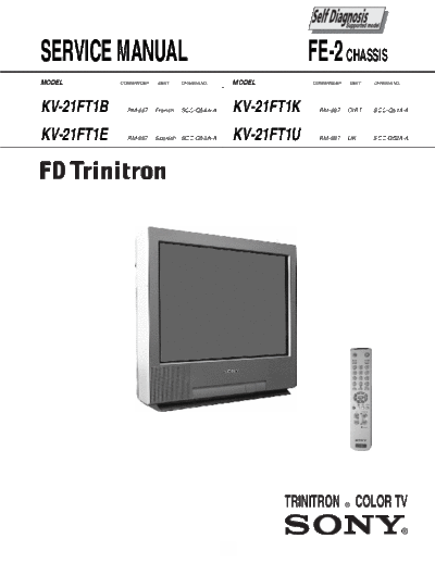
Image preview - the first page of the document

>> Download kv-21ft1 documenatation <<
Text preview - extract from the document
SERVICE MANUAL                                                 FE-2 CHASSIS
MODEL       COMMANDER   DEST     CHASSIS NO.       MODEL       COMMANDER   DEST            CHASSIS NO.


KV-21FT1B     RM-887    French   SCC-Q54A-A        KV-21FT1K     RM-887    OIRT            SCC-Q51A-A


KV-21FT1E     RM-887    Spanish SCC-Q53A-A         KV-21FT1U     RM-887    UK              SCC-Q52A-A


                                                                                  RM-889


                                               1
                                                           TABLE OF CONTENTS

Section      Title                                                    Page       Section       Title                                             Page
             Specifications                    ....................   3          3. SET-UP ADJUSTMENTS
             Connectors                        ....................   5                3-1. Beam Landing                  ....................   14
             Self Diagnostic Software          ....................   6                3-2. Convergence                   ....................   15
                                                                                       3-3. Focus Adjustment              ....................   17
1. GENERAL                                                                             3-4. Screen (G2), White Balance    ....................   17
             Switching On the TV and
             Automatically Tuning        ....................         7          4. CIRCUIT ADJUSTMENTS
             Introducing the Menu System ....................         8                4-1.  Electrical Adjustments       ....................   18
             Teletext                    ....................         10               4-2.  Test Mode 2                  ....................   20
             Connecting Optional Equipment....................        10
             Using Optional Equipment    ....................         10         5. DIAGRAMS
             Specifications              ....................         11               5-1. Circuit Board Location        ....................   22
             Troubleshooting              ....................        11               5-2. Block Diagrams                ....................   23
                                                                                       5-3. Schematic Diagrams and
2. DISASSEMBLY                                                                              Printed Wiring Boards         ....................   27
      2-1. Rear Cover Removal                  ....................   12                            * C Board             ....................   27
      2-2. Chassis Removal                     ....................   12                            * A Board             ....................   29
      2-3. Service Position                    ....................   12               5-4. Semiconductors                ....................   37
      2-4. Wire Dressing                       ....................   12               5-5. IC Blocks                     ....................   39
      2-5. Picture Tube Removal                ....................   13
                                                                                 6. EXPLODED VIEWS
                                                                                       6-1. Chassis                       ....................   40
                                                                                       6-2. Picture Tube                  ....................   41

                                                                                 7. ELECTRICAL PARTS LIST                 ....................   42


                             CAUTION                                                                       ATTENTION

SHORT CIRCUIT THE ANODE OF THE PICTURE TUBE AND THE                              APRES AVOIR DECONNECTE LE CAP DE'LANODE,
ANODE CAP TO THE METAL CHASSIS, CRT SHIELD, OR THE                               COURT-CIRCUITER L'ANODE DU TUBE CATHODIQUE ET CELUI
CARBON PAINTED ON THE CRT, AFTER REMOVAL OF THE                                  DE L'ANODE DU CAP AU CHASSIS METALLIQUE DE L'APPAREIL,
ANODE CAP.                                                                       OU AU COUCHE DE CARBONE PEINTE SUR LE TUBE
                                                                                 CATHODIQUE OU AU BLINDAGE DU TUBE CATHODIQUE.

                           WARNING !!
                                                                                                           ATTENTION !!
AN ISOLATION TRANSFORMER SHOULD BE USED DURING ANY
SERVICE WORK TO AVOID POSSIBLE SHOCK HAZARD DUE TO                               AFIN D'EVITER TOUT RISQUE D'ELECTROCUTION PROVENANT
LIVE CHASSIS, THE CHASSIS OF THIS RECEIVER IS DIRECTLY                           D'UN CH
◦ Jabse Service Manual Search 2024 ◦ Jabse Pravopis ◦ onTap.bg ◦ Other service manual resources online : Fixya ◦ eServiceinfo