Service Manuals, User Guides, Schematic Diagrams or docs for : Sony Sony STR-1015G receiver
<< Back | HomeMost service manuals and schematics are PDF files, so You will need Adobre Acrobat Reader to view : Acrobat Download Some of the files are DjVu format. Readers and resources available here : DjVu Resources
For the compressed files, most common are zip and rar. Please, extract files with Your favorite compression software ( WinZip, WinRAR ... ) before viewing. If a document has multiple parts, You should download all, before extracting.
Good luck. Repair on Your own risk. Make sure You know what You are doing.
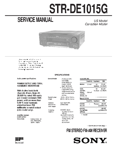
Image preview - the first page of the document

>> Download Sony STR-1015G receiver documenatation <<
Text preview - extract from the document
              STR-DE1015G
  SERVICE MANUAL                              US Model
                                         Canadian Model


                   SPECIFICATIONS


                                           -- Continued on next page --


                               FM STEREO FM-AM RECEIVER

MICROFILM


                       --1--
--2--
                         TABLE OF CONTENTS                                                                            SAFETY CHECK-OUT

1. SERVICING NOTE .......................................................... 4                   After correcting the original service problem, perform the follow-
                                                                                                 ing safety checks before releasing the set to the customer:
                                                                                                 Check the antenna terminals, metal trim, "metallized" knobs, screws,
2. GENERAL .......................................................................... 5
                                                                                                 and all other exposed metal parts for AC leakage. Check leakage as
                                                                                                 described below.
3. DISASSEMBLY
3-1. Front Panel .......................................................................... 26   LEAKAGE
3-2. Balance Board, Display Board and Volume Board ............. 26                              The AC leakage from any exposed metal part to earth Ground and
                                                                                                 from all exposed metal parts to any exposed metal part having a
4. TEST MODE ..................................................................... 27            return to chassis, must not exceed 0.5 mA (500 microampers). Leak-
                                                                                                 age current can be measured by any one of three methods.
5. ELECTRICAL ADJUSTMENTS ............................... 28                                     1. A commercial leakage tester, such as the Simpson 229 or RCA
                                                                                                    WT-540A. Follow the manufacturers' instructions to use these
6. DIAGRAMS                                                                                         instruments.
6-1. IC Pin Functions ................................................................. 30       2. A battery-operated AC milliammeter. The Data Precision 245
6-2. Circuit Boards Location ...................................................... 47              digital multimeter is suitable for this job.
6-3. Block Diagrams                                                                              3. Measuring the voltage drop across a resistor by means of a VOM
◦ Jabse Service Manual Search 2024 ◦ Jabse Pravopis ◦ onTap.bg ◦ Other service manual resources online : Fixya ◦ eServiceinfo