Service Manuals, User Guides, Schematic Diagrams or docs for : Sony Sony TA-VE810G
<< Back | HomeMost service manuals and schematics are PDF files, so You will need Adobre Acrobat Reader to view : Acrobat Download Some of the files are DjVu format. Readers and resources available here : DjVu Resources
For the compressed files, most common are zip and rar. Please, extract files with Your favorite compression software ( WinZip, WinRAR ... ) before viewing. If a document has multiple parts, You should download all, before extracting.
Good luck. Repair on Your own risk. Make sure You know what You are doing.
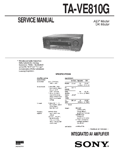
Image preview - the first page of the document

>> Download Sony TA-VE810G documenatation <<
Text preview - extract from the document
                         TA-VE810G
  SERVICE MANUAL                                    AEP Model
                                                     UK Model


                   SPECIFICATIONS


                                              -- Continued on next page --


                                    INTEGRATED AV AMPLIFIER

MICROFILM


                       --1--
                                                                                  TABLE OF CONTENTS

                                                        1. SERVICING NOTE .......................................................... 3

                                                        2. GENERAL .......................................................................... 4

                                                        3. DISASSEMBLY
                                                        3-1. Front Panel .......................................................................... 22
                                                        3-2. Balance Board, Display Board and Volume Board ............. 22

                                                        4. ELECTRICAL ADJUSTMENTS ............................... 23

                                                        5. DIAGRAMS
                                                        5-1. Circuit Boards Location ...................................................... 24
                                                        5-2. Printed Wiring Board -- Dolby Surround Section -- ........ 26
                                                        5-3. Schematic Diagram -- Dolby Surround Section -- ........... 29
                                                        5-4. Schematic Diagram -- OSD Section -- ............................. 33
                                                        5-5. Printed Wiring Board -- OSD Section -- .......................... 37
                                                        5-6. Printed Wiring Board -- Power Amp Section -- ............... 41
                                                        5-7. Schematic Diagram -- Power Amp Section -- .................. 45
                                                        5-8. Schematic Diagram -- Panel Section -- ............................ 49
                                                        5-9. Printed Wiring Board -- Panel Section -- ......................... 53
                                                        5-10. IC Block Diagrams ........................................................... 57
                                                        5-11. IC Pin Functions ............................................................... 62

                                                        6. EXPLODED VIEWS
                                                        6-1.   Case Section ........................................................................ 69
                                                        6-2.   Front panel Section ............................................................. 70
                                                        6-3.   OSD Board Section ............................................................. 71
                                                        6-4.   Chassis Section ................................................................... 72

                                                        7. ELECTRICAL PARTS LIST ........................................ 73


MODEL IDENTIFICATION
-- BACK PANEL --


                                                        Notes on chip component replacement
◦ Jabse Service Manual Search 2024 ◦ Jabse Pravopis ◦ onTap.bg ◦ Other service manual resources online : Fixya ◦ eServiceinfo