Service Manuals, User Guides, Schematic Diagrams or docs for : Sony sony tv bulletins sony tv bulletins TVP0281
<< Back | HomeMost service manuals and schematics are PDF files, so You will need Adobre Acrobat Reader to view : Acrobat Download Some of the files are DjVu format. Readers and resources available here : DjVu Resources
For the compressed files, most common are zip and rar. Please, extract files with Your favorite compression software ( WinZip, WinRAR ... ) before viewing. If a document has multiple parts, You should download all, before extracting.
Good luck. Repair on Your own risk. Make sure You know what You are doing.
Image preview - the first page of the document

>> Download TVP0281 documenatation <<
Text preview - extract from the document
                                  TV Products                                                         CSV-1
                                  Service Bulletin
                                   Sony Service Company - Technical Services
                                   A Division of Sony Electronics Inc.
                                   Sony Drive, Park Ridge, New Jersey 07656


Model:      KP-41T15, 46S15, 53S15, 46V25, 53V25                                 No.       281R2
            KP-61V25, 53XBR45, 61XBR48

Subject: Circuit Improvement to CR, CG, CB Boards                                Date: April 29, 1996


Symptom:
 (111)         Unit has no picture (shutdown) and requires IC701, IC731 or IC761 (Video output IC)
               replacement.

Parts List:    This Service Bulletin is required following additional components:

                       DESCRIPTION                             PART NUMBER         Q'TY             REMARKS

                       TDA6101Q/N3                                8-759-346-42         3
              CERAMIC, CAP, 50V, 0.047UF                          1-101-006-00         3
              CERAMIC, CAP, 500V, 0.01UF                          1-102-050-00         3
                      DIODE, RD13ESB2                             8-719-110-36         3
                       DIODE, 1SS83                               8-719-901-83         3
                1 OHM, 1/2W, RESISTOR                            1-249-474-11          1     SEE S/B TVP 291R1
               0.47 OHM, 1/2W, RESISTOR                          1-260-288-11          1     SEE S/B TVP 291R1


Solution:      1. Part number of Video output IC had been changed, Please replace all 3 ICs with
               new type.

                      REF                 FORMER                                           NEW
                             DESCRIPTION          PART NUMBER               DESCRIPTION      PART NUMBER

                  IC701        TDA6101Q              8-759-168-72           TDA6101Q/N3          8-759-346-42
                  IC731
                  IC761
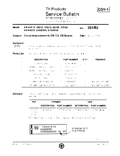
               Note: New IC has marking "3" in the following location. Please check IC type.


                                                                                                    (Cont.)

Reference: PTG Kiga                                                                                 PRINTED IN USA

                                               PRINTED ON RECYCLED PAPER
TV Products Service Bulletin No.281R2


                 2. Please add the following components to CR, CG and CB Boards.

                  LOCATION OF COMPONENT                         ADDITIONAL COMPONENT
                       (IC701, IC731, IC761)                DESCRIPTION                 PART NUMBER
                      BETWEEN PIN 2 AND 4           CERAMIC, CAP, 50V, 0.047UF           1-101-006-00
                      BETWEEN PIN 4 AND 6           CERAMIC, CAP, 500V, 0.01UF           1-102-050-00
                      BETWEEN PIN 2 AND 4                 DIODE, RD13ESB2                8-719-110-36

                 Note: Diode and capacitors above should apply to IC pins directly. Please refer to
                 illustration on next page.
                 Some of the above components may have already been added by factory.
                 Add any that are necessary.

                 3. Please add following Diode to CR, CG and CB Board.

                          REF. NUMBER                           ADDITIONAL COMPONENT
                                                            DESCRIPTION                PART NUMBER

                         D715, CR BOARD                    DIODE, 1SS83TD                8-719-901-83
                         D735, CG BOARD                    DIODE, 1SS83TD                8-719-901-83
                         D767, CB BOARD                    DIODE, 1SS83TD                8-719-901-83


                 4. Please apply additional changes for TVP0291R1.
◦ Jabse Service Manual Search 2024 ◦ Jabse Pravopis ◦ onTap.bg ◦ Other service manual resources online : Fixya ◦ eServiceinfo