Service Manuals, User Guides, Schematic Diagrams or docs for : Sony sony tv bulletins sony tv bulletins TVP0204
<< Back | HomeMost service manuals and schematics are PDF files, so You will need Adobre Acrobat Reader to view : Acrobat Download Some of the files are DjVu format. Readers and resources available here : DjVu Resources
For the compressed files, most common are zip and rar. Please, extract files with Your favorite compression software ( WinZip, WinRAR ... ) before viewing. If a document has multiple parts, You should download all, before extracting.
Good luck. Repair on Your own risk. Make sure You know what You are doing.
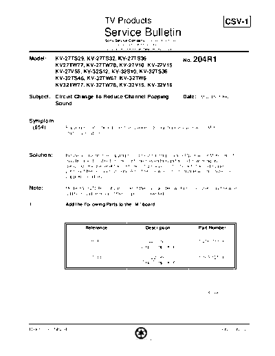
Image preview - the first page of the document

>> Download TVP0204 documenatation <<
Text preview - extract from the document
                                   TV Products                                                    CSV-1
                                   Service Bulletin
                                   Sony Service Company - Technical Services
                                   A Division of Sony Electronics Inc.
                                   Sony Drive, Park Ridge, New Jersey 07656

Model:      KV-27TS29, KV-27TS32, KV-27TS36                                    No. 204R1
            KV27TW77, KV-27TW78, KV-27V10, KV-27V15
            KV-27V55, KV-32S12, KV-32S10, KV-32TS36
            KV-32TS46, KV-32TW67, KV-32TW6
            KV32TW77, KV-32TW78, KV-32V15, KV-32V16

Subject: Circuit Change To Reduce Channel Popping                              Date: May 15, 1996
         Sound


Symptom:
 (654)         Popping sound is heard from the speakers during channel Up/Down or Mute
               On/Off activation.


Solution:      In rare occasions, the popping sound heard during channel Up/Down or Mute On/Off
               may be objectionable to some customers even though the unit is working as
               designed. Please reset the customers bass level control back to the mid range
               position if the setting is at high. Also, the following circuit change will minimize the
               popping sound level.

Note:          Model KV-32TS46 contains some of the changes below. In some cases only the wire
               additions and removal of the jumpers are needed.

1.             Add the Following Parts to the "M" board.


                         Reference                             Description           Part Number


                            R010                              220 ohm                1-216-033-00
                                                         (Chip Component)

                            C011                              220 PF                 1-163-125-00
                                                         (Chip Component)


                                                                                         Cont.


Reference: SB204                                                                              PRINTED IN USA

                                               PRINTED ON RECYCLED PAPER
TV Products Service Bulletin No. 204R1


2.               Add the Following parts to the UA Board.


                       Reference              Description            Part Number


                     Q402                2SD-601A (Chip Type)    8-729-422-28

                     Q403                2SD-601A (Chip Type)    8-729-422-28

                     D413                RD-3.3ESB               8-719-109-66

                     R428                3.3K ohm (Chip Type)    1-216-061-00

                     R430                3.3K ohm (Chip Type)    1-216-061-00

                     R438                0 Ohm (Chip Type)       1-216-295-00

                     C423                1.0 MF/50V              1-124-903-11

3.               Eliminate the following components from the "D" Board.
TV Products Service Bulletin No. 204R1


                       Reference               Description

                        C2202             Jumper Wire (5 MM)

                        C2204             Jumper Wire (5 MM)


4.                 Add the Following wires between the "D" Board and "UA" Board.

         Description                Length                     Location              Location
                                                                (From)                 (To)

     Wire, AWG 24 or 26            11 inches                 C417 (-)                C2204 (-)
                                                             UA Board                "D" Board

     Wire, AWG 24 or 26            11 inches                 C418 (-)                C2202 (-)
                                                             UA Board                "D" Board


 Note: When soldering a chip component, if the soldering iron is applied for too long a time, the
       heat from the iron can damage the chip component. A low heat soldering iron is available
       through Sony Parts. Part Number J-6080-801-A
◦ Jabse Service Manual Search 2024 ◦ Jabse Pravopis ◦ onTap.bg ◦ Other service manual resources online : Fixya ◦ eServiceinfo