Service Manuals, User Guides, Schematic Diagrams or docs for : Sony sony tv bulletins sony tv bulletins TVP0460
<< Back | HomeMost service manuals and schematics are PDF files, so You will need Adobre Acrobat Reader to view : Acrobat Download Some of the files are DjVu format. Readers and resources available here : DjVu Resources
For the compressed files, most common are zip and rar. Please, extract files with Your favorite compression software ( WinZip, WinRAR ... ) before viewing. If a document has multiple parts, You should download all, before extracting.
Good luck. Repair on Your own risk. Make sure You know what You are doing.
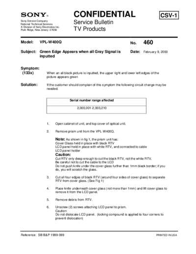
Image preview - the first page of the document

>> Download TVP0460 documenatation <<
Text preview - extract from the document
                                            CONFIDENTIAL                                                    CSV-1
Sony Service Company
National Technical Services                 Service Bulletin
A Division of Sony Electronics Inc.
Park Ridge, New Jersey 07656                TV Products

Model:          VPL-W400Q                                                             No.    460
Subject: Green Edge Appears when all Gray Signal is                                   Date: February 9, 2000
         inputted


Symptom:
 (133x)                When an all black picture is inputted, the upper right and lower left edges of the
                       picture appears green

Solution:              If the customer should complain of this symptom the following circuit change may be
                       needed.


                                         Serial number range affected

                                              2,000,001-2,003,210


                       1.      Open cabinet of unit, and top cover of optical unit.

                       2.      Remove prism unit from the VPL-W400Q.

                               Note: As shown in fig 1, the prism unit has:
                               Cover Glass-held in place with black RTV
                               LCD panel-held in place with white RTV, and connected to cable
                               LCD panel holder
                               Caution:
                               Cut RTV only deep enough to cut the black RTV, not the white RTV.
                               Be careful not to cut the cable to the LCD
                               Do not push knife under the cover glass further than 1mm black border; if you
                               do, you will scratch the glass.

                       3.      Cut all four edges of black RTV (around four sides of cover glass) to separate
                               RTV from cover glass. (See Fig 1)

                       4.      Place knife underneath cover glass (not more than 1mm) and lift cover glass to
                               remove it from the LCD panel.

                       5.      Remove debris from RTV.

                       6.      Unscrew (2) screws attaching LCD panel to prism.
                               Caution:
                               Do not dislocate LCD panel. (locking compound is applied to four corners to
                               prevent dislocation)


Reference: SB B&P 1999-099                                                                             PRINTED IN USA
TV Products Service Bulletin No. 460


                 7.    Insert plate over LCD panel in place of cover glass.

                 8.    Tighten two screws attaching LCD panel to prism.

                 9.    Implement steps 3 through 8 for three panels of R, G, and B.

                 10.   Assemble optical unit.


                   Description           Part Number               Quantity

                       Plate             4-070-318-01                 3


                                                           Fig 1
◦ Jabse Service Manual Search 2024 ◦ Jabse Pravopis ◦ onTap.bg ◦ Other service manual resources online : Fixya ◦ eServiceinfo