Service Manuals, User Guides, Schematic Diagrams or docs for : Sony sony tv bulletins sony tv bulletins TVP0475
<< Back | HomeMost service manuals and schematics are PDF files, so You will need Adobre Acrobat Reader to view : Acrobat Download Some of the files are DjVu format. Readers and resources available here : DjVu Resources
For the compressed files, most common are zip and rar. Please, extract files with Your favorite compression software ( WinZip, WinRAR ... ) before viewing. If a document has multiple parts, You should download all, before extracting.
Good luck. Repair on Your own risk. Make sure You know what You are doing.
Image preview - the first page of the document

>> Download TVP0475 documenatation <<
Text preview - extract from the document
                                         CONFIDENTIAL                                                  CSV-1
Sony Service Company
National Technical Services              Service Bulletin
A Division of Sony Electronics Inc.
Park Ridge, New Jersey 07656             TV Products

Model:          KV-32S40, KV-32V40, KV-32S45                                     No.      475
                KV-35S40, KV-35S45

Subject: Service Manual Update                                                   Date: March 24, 2000


Symptom:
 (1311)                The following Service Manual update is being issued since the S/M was written
                       before the circuit change was made. Therefore the circuit change was not shown in
                       the Service Manual.

                       This circuit change to IC501 was implemented from the start of production. To
                       prevent the following symptom.

                       If the TV is turned OFF/ON the hold down circuit might not have discharged enough
                       to release the protection circuit. Thereby the LED would continue to blink and no
                       picture present.

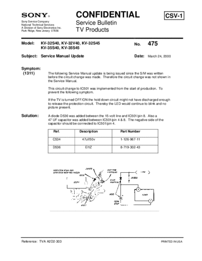
Solution:              A diode D536 was added between the 15-volt line and IC501/pin 8. Also a
                       47 UF capacitor was added between IC501/pin 4 & 8. The negative side of the
                       capacitor should be connected to IC501/pin 4.

                            Ref.            Description                Part Number

                           C534              47uf/50v                  1-126-967-11

                           D536                El1Z                    8-719-302-43


Reference: TVA A2D2-303                                                                           PRINTED IN USA
◦ Jabse Service Manual Search 2024 ◦ Jabse Pravopis ◦ onTap.bg ◦ Other service manual resources online : Fixya ◦ eServiceinfo