Service Manuals, User Guides, Schematic Diagrams or docs for : Sony sony tv bulletins sony tv bulletins TVP0482
<< Back | HomeMost service manuals and schematics are PDF files, so You will need Adobre Acrobat Reader to view : Acrobat Download Some of the files are DjVu format. Readers and resources available here : DjVu Resources
For the compressed files, most common are zip and rar. Please, extract files with Your favorite compression software ( WinZip, WinRAR ... ) before viewing. If a document has multiple parts, You should download all, before extracting.
Good luck. Repair on Your own risk. Make sure You know what You are doing.
Image preview - the first page of the document

>> Download TVP0482 documenatation <<
Text preview - extract from the document
                                          CONFIDENTIAL                                                   CSV-1
Sony Service Company
National Technical Services               Service Bulletin
A Division of Sony Electronics Inc.
Park Ridge, New Jersey 07656              TV Products

Model:          KWP-65HD1                                                          No.           482
Subject: Faint Vertical Bars on Screen.                                            Date: June 6, 2000


Symptom:
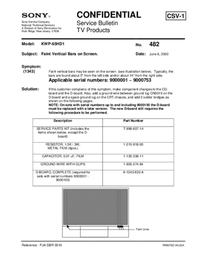
 (1343)                Faint vertical bars may be seen on the screen (see illustration below). Typically, the
                       bars are found about 5" from the left side and/or about 14" from the right side.
                       Applicable serial numbers: 9000001 ~ 9000753
Solution:              If the customer complains of this symptom, make component changes to the CG-
                       board and the D-board. Also, add a ground wire between ground lug CN5015 on the
                       D-board and a spare ground lug on the CRT chassis, and add 2 solder bridges as
                       shown on the following pages.
                       NOTE: On sets with serial numbers up to and including 9000150 the D-board
                       must be replaced with a later version. The new D-board still requires the
                       following procedure to be performed.

                           Description                                    Part Number

            SERVICE PARTS KIT (includes the                               T-998-607-14
             items shown below, except the D-
                         board)

                    RESISTOR, 1.5K / 3W,                                  1-215-918-00
                     METAL FILM (6pcs.)

                 CAPACITOR, 0.01 uF, FILM                                 1-130-338-11

                GROUND WIRE WITH CLIPS                                    1-900-274-84

            D-BOARD, COMPLETE (required for                               A-1343-620-A
             sets with serial numbers 9000001 -
                          9000150)


                                                                                   Faint Lines


Reference: PJA SBR 0010                                                                                PRINTED IN USA
TV Products Service Bulletin No. 482
                  Remove solder resist from the 2
                  patterns along side of CN5015,
                  then bridge the 2 patterns
                  together with solder. Be careful
                  not to short to Q5033!
                                                                Q5033
                                                   CN5015


                                   D-Board Solder Side


       Also add a solder                                    Add solder
       bridge to these                    Remove            bridge across
       ground patterns.                   solder-resist     patterns.
                                          from patterns.
TV Products Service Bulletin No. 482


         D-Board Component Side
                                                      Replace C8012
                                                      with 0.01uF
                                                      (supplied with
                                                      parts kit).


     Replace R8012, R8016, and R8020 with 3 pairs
     of 1.5K / 3W resistors as shown (resistors are
     supplied with parts kit). Each individual pair
     should be twisted together and soldered at the
     junction. Do not solder one pair to another!
TV Products Service Bulletin No. 482


                                  CG Board (Component Side)
                                   R7218 Mounting Location


                            R7218


           CG Board (Solder Side)
        R7218 New Mounting Location


  2- Move
  R7218 here.
                                 1- Unsolder R7218
                                 from these 2 pads.
TV Products Service Bulletin No. 482


                                 D-Board Component Side


                                                                  Ground lug
                                                                  CN5015


                                                             Connect one end of the
                                                             ground wire supplied
                                                             with the parts kit to
                                                             CN5015.


                                                    Connect the other end of
                                                    the ground wire to a spare
                                                    ground lug on this corner
                                                    of the CRT chassis.


                                                      Route the ground wire
                                                      through the purse locks
                                                      along the front edge of
                                                      the A-Board.


    Perform a full check of the TV's operations after performing the
    changes on the previous pages.
◦ Jabse Service Manual Search 2024 ◦ Jabse Pravopis ◦ onTap.bg ◦ Other service manual resources online : Fixya ◦ eServiceinfo