Service Manuals, User Guides, Schematic Diagrams or docs for : Sony sony tv bulletins sony tv bulletins TVP0523
<< Back | HomeMost service manuals and schematics are PDF files, so You will need Adobre Acrobat Reader to view : Acrobat Download Some of the files are DjVu format. Readers and resources available here : DjVu Resources
For the compressed files, most common are zip and rar. Please, extract files with Your favorite compression software ( WinZip, WinRAR ... ) before viewing. If a document has multiple parts, You should download all, before extracting.
Good luck. Repair on Your own risk. Make sure You know what You are doing.
Image preview - the first page of the document
>> Download TVP0523 documenatation <<
Text preview - extract from the document
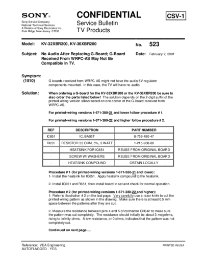
                                           CONFIDENTIAL                                                     CSV-1
Sony Service Company
National Technical Services                Service Bulletin
A Division of Sony Electronics Inc.
Park Ridge, New Jersey 07656               TV Products

Model:          KV-32XBR200, KV-36XBR200                                             No.       523
Subject: No Audio After Replacing G-Board; G-Board                                   Date: February 2, 2001
         Received From WRPC-AS May Not Be
         Compatible In TV.


Symptom:
 (1510)                G-boards received from WRPC-AS might not have the audio 5V regulator
                       components mounted. In this case, the TV will have no audio.

Solution:              When ordering a G-board for the KV-32XBR200 or the KV-36XBR200 be sure to
                       also order the parts listed below! The solution depends on the 2-digit suffix of the
                       printed-wiring version silkscreened on one corner of the G-board received from
                       WRPC-AS.

                       For printed-wiring versions 1-671-380-21 and lower follow procedure # 1.

                       For printed-wiring versions 1-671-380-22 and higher follow procedure # 2.

                      REF                 DESCRIPTION                             PART NUMBER
                     IC651                   IC, BA05T                              8-759-450-47
                     R651         RESISTOR 33 OHM, 5%, 3 WATT                       1-215-908-00
                        -             HEATSINK FOR IC651                 REUSE FROM ORIGINAL BOARD
                        -             SCREW W/ WASHERS                   REUSE FROM ORIGINAL BOARD
                        -             HEATSINK COMPOUND                          OBTAIN LOCALLY

                       Procedure # 1 (for printed-wiring versions 1-671-380-21 and lower):
                       1- Install the heatsink for IC651. Apply heatsink compound to the heatsink.

                       2- Install IC651 and R651, then install board in set and check for normal operation.

                       Procedure # 2 (for printed-wiring versions 1-671-380-22 and higher):
                       1- Refer to illustration # 2 on the last page. Very carefully use a razor knife to cut the
                       printed-wiring pattern as shown in the drawing. Make sure there is at least 0.5 mm
                       space between the patterns after they are cut.

                       2- Measure the resistance between pins 4 and 5 of connector CN642 to make sure
                       the pattern was cut completely. The resistance should initially be about 3 megohms,
                       rising to infinity ohms. A low resistance, or 0 ohms, indicates that the pattern was not
                       completely cut.

                       Continued on next page....


Reference: VEA Engineering                                                                               PRINTED IN USA
AUTOFLAGGED - YES
TV Products Service Bulletin No. 523


                 3- Install the heatsink for IC651. Apply heatsink compound to the heatsink.

                 4- Install IC651 and R651, then install board in set and check for normal operation.


                 Mounting Locations For IC651 And Heatsink, And For R651.


                                                   Holes for mounting heatsink.


                    Holes for
                    mounting
                    R651.
                                                  Holes for
                                                  mounting
                                                  IC651.


                                            Illustration # 1


                                       Continued on next page....
   TV Products Service Bulletin No. 523

          G-board With Printed-wiring Pattern Version -22 And Higher.
          Last 2 digits of the top number indicate printed-wiring version. For example,
          number 1-671-380-22 indicates version -22 printed-wiring pattern.


                                                               Caution: make sure you do
                                                               not cut these thin patterns!


                                                                Minimum space
                                                                between patterns after
Cut the printed wiring pattern as                               cutting is 0.5 mm.
indicated by the dotted line.


                                          Illustration # 2
◦ Jabse Service Manual Search 2024 ◦ Jabse Pravopis ◦ onTap.bg ◦ Other service manual resources online : Fixya ◦ eServiceinfo