Service Manuals, User Guides, Schematic Diagrams or docs for : clarion AB223R Clarion_AB223R_AB223RG

<< Back | Home

Most service manuals and schematics are PDF files, so You will need Adobre Acrobat Reader to view : Acrobat Download Some of the files are DjVu format. Readers and resources available here : DjVu Resources
For the compressed files, most common are zip and rar. Please, extract files with Your favorite compression software ( WinZip, WinRAR ... ) before viewing. If a document has multiple parts, You should download all, before extracting.
Good luck. Repair on Your own risk. Make sure You know what You are doing.


Image preview - the first page of the document
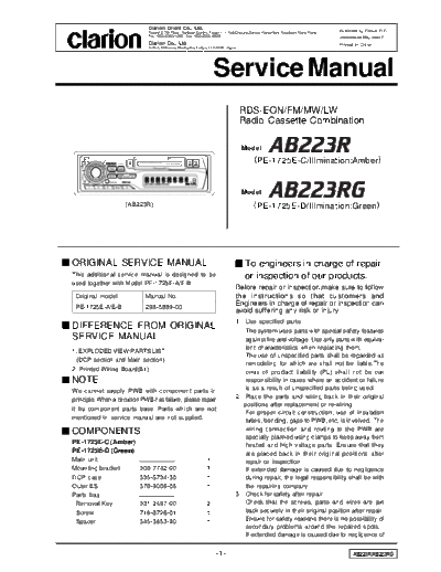
Clarion_AB223R_AB223RG


>> Download Clarion_AB223R_AB223RG documenatation <<

Text preview - extract from the document
                                       Clarion Orient Co., Ltd.
                                       Room12, 7th Floor, Harbour Centre, Tower 1, 1 Hok Cheung Street, Hung Hom, Kowloon, Hong Kong
                                                                                                                                       Published by Clarion O.C.
                                       Tel.: 852-2303-1395, Fax: 852-2365-9929                                                         298-5990-00 May. 2002 P
                                       Clarion Co., Ltd.                                                                               Printed in China
                                       5-35-2, Hakusan, Bunkyoku, Tokyo, 112-8608 Japan


                                                                              Service Manual
                                                                                          RDS-EON/FM/MW/LW
                                                                                          Radio Cassette Combination

                                                                                          Model

                  AB223R       TUNER CASSETTE PLAYER   HIGH POWER 40WX4
                                                                                                 ( PE-1725E-C/Illmination:Amber )


                                                                                          Model
                           (AB223R)                                                              ( PE-1725E-D/Illmination:Green)


ORIGINAL SERVICE MANUAL                                                                     To engineers in charge of repair
This additional service manual is designed to be                                            or inspection of our products.
used together with Model PE-1725E-A/E-B.
                                                                                       Before repair or inspection,make sure to follow
 Original model                     Manual No.                                         the instructions so that customers and
 PE-1725E-A/E-B                     298-5889-00
                                                                                       Engineers in charge of repair or inspection can
                                                                                       avoid suffering any risk or injury.
                                                                                       1. Use specified parts.
DIFFERENCE FROM ORIGINAL
                                                                                          The system uses parts with special safety features
SERVICE MANUAL                                                                            against fire and voltage. Use only parts with equiva-
                                                                                          lent characteristics when replacing them.
1. EXPLODED VIEW.PARTS LIST
                                                                                          The use of unspecified parts shall be regarded as
 (DCP section and Main section)
                                                                                          remodeling for which we shall not be liable.The
2. Printed Wiring Board(B1)                                                               onus of product liability (PL) shall not be our
NOTE                                                                                      responsibility in cases where an accident or failure
We cannot supply PWB with component parts in                                              is as a result of unspecified parts being used.
                                                                                       2. Place the parts and wiring back in their original
principle. When a circuit on PWB has failure, please repair
                                                                                          positions after replacement or re-wiring.
it by component parts base. Parts which are not
                                                                                          For proper circuit construction, use of insulation
mentioned in service manual are not supplied.
                                                                                          tubes, bonding, gaps to PWB, etc, is involved. The
                                                                                          wiring connection and routing to the PWB are
COMPONENTS
                                                                                          specially planned using clamps to keep away from
PE-1725E-C (Amber)                                                                        heated and high voltage parts. Ensure that they
PE-1725E-D (Green)                                                                        are placed back in their original positions after
Main unit                                                                 1               repair or inspection.
Mounting bracket               300-7742-00                                1               If extended damage is caused due to negligence
DCP case                       335-5734-30                                1               during repair, the legal responsibility shall be with
Outer ES                       370-9006-08                                1               the repairing company.
Parts bag                                                                              3. Check for safety after repair.
 Removal Key                   331-2497-00                                2               Check that the screws, parts and wires are put
 Screw                         716-0726-01                                1               back securely in their original position after repair.
 Spacer                        345-3653-20                                1               Ensure for safety reasons there is no possibility of
                                                                                          secondary problems around the repaired spots.
                                                                                          If extended damage is caused due to negligence of

                                                                              -1-                                                            AB223R/AB223RG
      repair, the legal responsibility shall be with the re-                                          resistors, capacitors, diodes, transistors, etc). The
      pairing company.                                                                               negative pole of tantalum capacitors is highly
   4. Caution in removal and making wiring connec-                                                   susceptible to heat, so use special care when
       tion to theparts for the automobile.                                                          replacing them and check the operation afterwards.
      Disconnect the battery terminal after turning the                                           6. Cautions in handling flexible PWB.
      ignition key off. If wrong wiring connections are                                               Before working with a soldering iron, make sure that
      made with the battery connected, a short circuit                                               the iron tip temperature is around 270


◦ Jabse Service Manual Search 2024 ◦ Jabse PravopisonTap.bg ◦ Other service manual resources online : FixyaeServiceinfo