Service Manuals, User Guides, Schematic Diagrams or docs for : panasonic Audio SC-ALL9 PSG1602013CE_PRINTDB
<< Back | HomeMost service manuals and schematics are PDF files, so You will need Adobre Acrobat Reader to view : Acrobat Download Some of the files are DjVu format. Readers and resources available here : DjVu Resources
For the compressed files, most common are zip and rar. Please, extract files with Your favorite compression software ( WinZip, WinRAR ... ) before viewing. If a document has multiple parts, You should download all, before extracting.
Good luck. Repair on Your own risk. Make sure You know what You are doing.
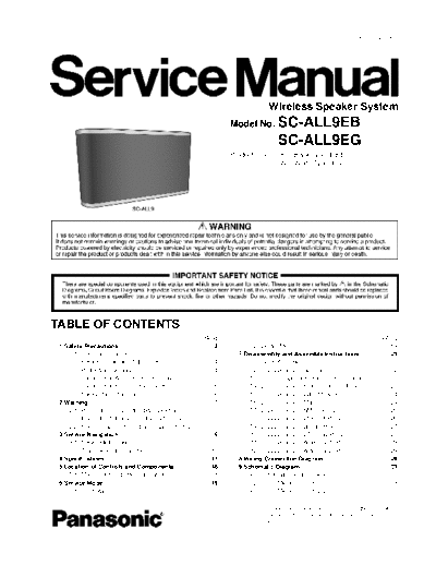
Image preview - the first page of the document

>> Download PSG1602013CE_PRINTDB documenatation <<
Text preview - extract from the document
                                                                                                                                    PSG1602013CE


                                                                                             Wireless Speaker System
                                                                              Model No. SC-ALL9EB
                                                                                                 SC-ALL9EG
                                                                              Product Color: (K)...Black Type (EB/EG)
                                                                                             (W)...White Type (EG)


TABLE OF CONTENTS
                                                                    PAGE                                                                       PAGE
 1 Safety Precautions----------------------------------------------- 3              6.2. Doctor Mode----------------------------------------------- 19
    1.1. General Guidelines---------------------------------------- 3           7 Disassembly and Assembly Instructions--------------- 21
    1.2. Before Repair and Adjustment ------------------------- 4                   7.1. Type of Screws ------------------------------------------- 21
    1.3. Protection Circuitry ---------------------------------------- 4            7.2. Disassembly Flow Chart ------------------------------- 22
    1.4. Caution For AC Cord (For EB only)------------------- 5                     7.3. Main Components and P.C.B. Locations----------- 22
    1.5. Caution For Fuse Replacement------------------------ 6                     7.4. Disassembly of Front Cabinet Block --------------- 23
    1.6. Safety Part Information----------------------------------- 6               7.5. Disassembly of WIFI Module-------------------------- 24
 2 Warning -------------------------------------------------------------- 7         7.6. Disassembly of Main P.C.B. --------------------------- 24
    2.1. Prevention of Electrostatic Discharge (ESD)                                7.7. Disassembly of SMPS P.C.B. ------------------------- 25
         to Electrostatically Sensitive (ES) Devices---------- 7                    7.8. Disassembly of Ethernet P.C.B. ---------------------- 26
    2.2. Service caution based on Legal restrictions -------- 8                     7.9. Disassembly of Bluetooth P.C.B.--------------------- 27
 3 Service Navigation ----------------------------------------------- 9           7.10. Disassembly of BT-Relay P.C.B. --------------------- 27
    3.1. Service Information --------------------------------------- 9             7.11. Disassembly of Antenna (1) P.C.B.------------------ 28
    3.2. Troubleshooting Guide ----------------------------------10               7.12. Disassembly of Antenna (2) P.C.B.------------------ 28
 4 Specifications ----------------------------------------------------17        8 Wiring Connection Diagram--------------------------------- 29
 5 Location of Controls and Components ------------------18                     9 Schematic Diagram -------------------------------------------- 31
    5.1. Main Unit Key Button Operations---------------------18                     9.1. Schematic Diagram Notes ----------------------------- 31
 6 Service Mode -----------------------------------------------------19             9.2. Main (Micon) Circuit (1/2) ------------------------------ 33
    6.1. Cold Start ---------------------------------------------------19           9.3. Main (Micon) Circuit (2/2) ------------------------------ 34
◦ Jabse Service Manual Search 2024 ◦ Jabse Pravopis ◦ onTap.bg ◦ Other service manual resources online : Fixya ◦ eServiceinfo