Service Manuals, User Guides, Schematic Diagrams or docs for : panasonic LED TH-32F400A Panasonic_TH-32F400A_TH-32F400Z_Chassis_KM36
<< Back | HomeMost service manuals and schematics are PDF files, so You will need Adobre Acrobat Reader to view : Acrobat Download Some of the files are DjVu format. Readers and resources available here : DjVu Resources
For the compressed files, most common are zip and rar. Please, extract files with Your favorite compression software ( WinZip, WinRAR ... ) before viewing. If a document has multiple parts, You should download all, before extracting.
Good luck. Repair on Your own risk. Make sure You know what You are doing.
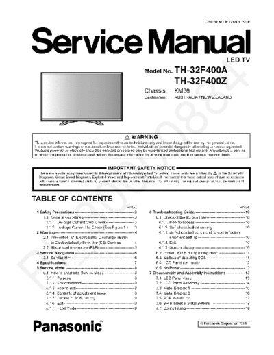
Image preview - the first page of the document

>> Download Panasonic_TH-32F400A_TH-32F400Z_Chassis_KM36 documenatation <<
Text preview - extract from the document
                                                                                                                         ORDER NO. MTV1801122CE


                                                                                                                                         LED TV
                                                                              Model No. TH-32F400A
                                                                                                  TH-32F400Z
                                                                              Chassis:            KM36
                                                                              Destination:        AUSTRALIA / NEW ZEALAND


TABLE OF CONTENTS
                                                                    PAGE                                                                            PAGE
 1 Safety Precautions----------------------------------------------- 3          6 Troubleshooting Guide --------------------------------------- 10
    1.1. General Guidelines---------------------------------------- 3               6.1. Check of the IIC bus lines------------------------------ 10
      1.1.1. Leakage Current Cold Check---------------------- 3                       6.1.1. How to access --------------------------------------- 10
      1.1.2. Leakage Current Hot Check (See Figure 1.) ---- 3                         6.1.2. Self-check indication only ------------------------- 10
 2 Warning -------------------------------------------------------------- 4           6.1.3. Self-check indication and forced to factory
    2.1. Prevention of Electrostatic Discharge (ESD)                                         shipment setting ------------------------------------- 10
         to Electrostatically Sensitive (ES) Devices---------- 4                      6.1.4. Exit ------------------------------------------------------ 10
    2.2. About lead free solder (PbF)---------------------------- 5                   6.1.5. Screen display --------------------------------------- 10
 3 Service Navigation ----------------------------------------------- 6             6.2. Power LED Blinking timing chart --------------------- 11
    3.1. Service Hint ------------------------------------------------- 6           6.3. Method of detecting SOS ------------------------------ 11
 4 Specifications ----------------------------------------------------- 7           6.4. LCD Panel test mode ----------------------------------- 12
 5 Service Mode ------------------------------------------------------ 8            6.5. No Power--------------------------------------------------- 12
    5.1. How to enter into Service Mode ----------------------- 8               7 Disassembly and Assembly Instructions--------------- 13
      5.1.1. Purpose ------------------------------------------------- 8            7.1. LED Panel Ass'y ----------------------------------------- 13
      5.1.2. Key command ----------------------------------------- 8                7.2. LCD Panel Assembly ----------------------------------- 14
      5.1.3. How to exit---------------------------------------------- 8            7.3. Metal Bracket 1 ------------------------------------------ 15
      5.1.4. Contents of adjustment mode --------------------- 8                    7.4. Metal Bracket 2 ------------------------------------------- 16
      5.1.5. Display of SOS History ------------------------------ 9                7.5. PCB Installation ------------------------------------------ 17
      5.1.6. Exit-------------------------------------------------------- 9         7.6. SP Bracket & Metal Bottom ------------------------- 18
      5.1.7. Hotel Mode --------------------------------------------- 9             7.7. Screw Fixing ---------------------------------------------- 19
◦ Jabse Service Manual Search 2024 ◦ Jabse Pravopis ◦ onTap.bg ◦ Other service manual resources online : Fixya ◦ eServiceinfo