Service Manuals, User Guides, Schematic Diagrams or docs for : . Car Manuals Nissan Maxima 2000-2005 Approved Nissan Maxima 2000 rs
<< Back | HomeMost service manuals and schematics are PDF files, so You will need Adobre Acrobat Reader to view : Acrobat Download Some of the files are DjVu format. Readers and resources available here : DjVu Resources
For the compressed files, most common are zip and rar. Please, extract files with Your favorite compression software ( WinZip, WinRAR ... ) before viewing. If a document has multiple parts, You should download all, before extracting.
Good luck. Repair on Your own risk. Make sure You know what You are doing.
Image preview - the first page of the document
>> Download rs documenatation <<
Text preview - extract from the document
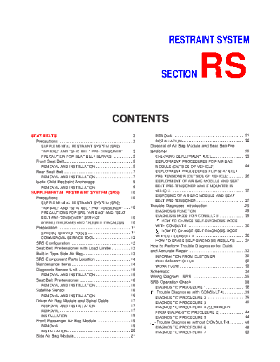
RESTRAINT SYSTEM
SECTION RS
CONTENTS
SEAT BELTS ...................................................................3 REMOVAL ...............................................................21
Precautions ..................................................................3 INSTALLATION........................................................22
SUPPLEMENTAL RESTRAINT SYSTEM (SRS) Disposal of Air Bag Module and Seat Belt Pre-
AIR BAG AND SEAT BELT PRE-TENSIONER ........3 tensioner ....................................................................22
PRECAUTION FOR SEAT BELT SERVICE ..................3 CHECKING DEPLOYMENT TOOL .............................23
Front Seat Belt.............................................................5 DEPLOYMENT PROCEDURES FOR AIR BAG
REMOVAL AND INSTALLATION .................................5 MODULE (OUTSIDE OF VEHICLE) ...........................24
Rear Seat Belt .............................................................7 DEPLOYMENT PROCEDURES FOR SEAT BELT
REMOVAL AND INSTALLATION .................................7 PRE-TENSIONER (OUTSIDE OF VEHICLE) ..............26
Isofix Child Restraint Anchorage .................................9 DEPLOYMENT OF AIR BAG MODULE AND SEAT
REMOVAL AND INSTALLATION .................................9 BELT PRE-TENSIONER WHILE MOUNTED IN
SUPPLEMENTAL RESTRAINT SYSTEM (SRS) .........10 VEHICLE .................................................................27
DISPOSING OF AIR BAG MODULE AND SEAT
Precautions ................................................................10
BELT PRE-TENSIONER ...........................................27
SUPPLEMENTAL RESTRAINT SYSTEM (SRS)
AIR BAG AND SEAT BELT PRE-TENSIONER ......10
Trouble Diagnoses Introduction.................................29
PRECAUTIONS FOR SRS AIR BAG AND SEAT DIAGNOSIS FUNCTION ...........................................29
BELT PRE-TENSIONER SERVICE...........................10 DIAGNOSIS MODE FOR CONSULT-II .......................29
WIRING DIAGRAMS AND TROUBLE DIAGNOSIS .....10 HOW TO CHANGE SELF-DIAGNOSIS MODE
WITH CONSULT-II ...................................................30
Preparation ................................................................11
HOW TO CHANGE SELF-DIAGNOSIS MODE
SPECIAL SERVICE TOOLS ......................................11
WITHOUT CONSULT-II ............................................30
COMMERCIAL SERVICE TOOL ................................12
HOW TO ERASE SELF-DIAGNOSIS RESULTS .........31
SRS Configuration .....................................................12
How to Perform Trouble Diagnoses for Quick
Seat Belt Pre-tensioner with Load Limiter.................13
and Accurate Repair ..................................................32
Built-in Type Side Air Bag..........................................13
INFORMATION FROM CUSTOMER ..........................32
SRS Component Parts Location ...............................14
PRELIMINARY CHECK ............................................32
Maintenance Items ....................................................14 WORK FLOW ..........................................................33
Diagnosis Sensor Unit ...............................................15 Schematic ..................................................................34
REMOVAL AND INSTALLATION ...............................15 Wiring Diagram - SRS -.............................................35
Seat Belt Pre-tensioner .............................................16 SRS Operation Check ...............................................38
REMOVAL AND INSTALLATION ...............................16
DIAGNOSTIC PROCEDURE 1 ..................................38
Satellite Sensor..........................................................16 Trouble Diagnoses with CONSULT-II...................39
REMOVAL AND INSTALLATION ...............................16
DIAGNOSTIC PROCEDURE 2 ..................................39
Driver Air Bag Module and Spiral Cable ...................17 DIAGNOSTIC PROCEDURE 3 ..................................42
REMOVAL AND INSTALLATION ...............................17 DIAGNOSTIC PROCEDURE 4 (CONTINUED
REMOVAL ...............................................................17 FROM DIAGNOSTIC PROCEDURE 2) ......................44
INSTALLATION........................................................19 DIAGNOSTIC PROCEDURE 5 ..................................44
Front Passenger Air Bag Module ..............................19 Trouble Diagnoses without CONSULT-II..............48
REMOVAL ...............................................................19 DIAGNOSTIC PROCEDURE 6 ..................................48
INSTALLATION........................................................20 DIAGNOSTIC PROCEDURE 7 ..................................53
Side Air Bag Module..................................................21
CONTENTS (Cont'd)
DIAGNOSTIC PROCEDURE 8 (CONTINUED DIAGNOSTIC PROCEDURE 10 ................................58
FROM DIAGNOSTIC PROCEDURE 6) ......................55 Collision Diagnosis ....................................................59
Trouble Diagnoses: AIR BAG Warning Lamp FOR FRONTAL COLLISION .....................................59
Does Not Turn Off .....................................................56 FOR SIDE COLLISION .............................................61
DIAGNOSTIC PROCEDURE 9 ..................................56
Trouble Diagnoses: AIR BAG Warning Lamp
Does Not Turn On .....................................................58
RS-2
SEAT BELTS
Precautions
Precautions
SUPPLEMENTAL RESTRAINT SYSTEM (SRS) "AIR BAG" AND "SEAT BELT
PRE-TENSIONER" NFRS0001
The Supplemental Restraint System such as "AIR BAG" and "SEAT BELT PRE-TENSIONER" used along with
a seat belt, helps to reduce the risk or severity of injury to the driver and front passenger for certain types of
collision. The SRS composition which is available to NISSAN MODEL A33 is as follows (The composition var-
ies according to optional equipment.):
+ For a frontal collision
The Supplemental Restraint System consists of driver air bag module (located in the center of the steer-
ing wheel), front passenger air bag module (located on the instrument panel on passenger side), seat belt
pre-tensioners, a diagnosis sensor unit, warning lamp, wiring harness and spiral cable.
+ For a side collision
The Supplemental Restraint System consists of front side air bag module (located in the outer side of front
seat), satellite sensor, diagnosis sensor unit (one of components of air bags for a frontal collision), wiring
harness, warning lamp (one of components of air bags for a frontal collision).
WARNING:
+ To avoid rendering the SRS inoperative, which could increase the risk of personal injury or death
in the event of a collision which would result in air bag inflation, all maintenance should be per-
formed by an authorized NISSAN dealer.
+ Improper maintenance, including incorrect removal and installation of the SRS, can lead to per-
sonal injury caused by unintentional activation of the system.
+ Do not use electrical test equipment on any circuit related to the SRS unless instructed to in this
Service Manual. Spiral cable and wiring harnesses covered with yellow insulation tape either just
before the harness connectors or for the complete harness are related to the SRS.
PRECAUTION FOR SEAT BELT SERVICE NFRS0002
CAUTION:
+ Before removing the seat belt pre-tensioner assembly, turn the ignition switch off, disconnect both
battery cables and wait at least 3 minutes.
+ Do not use electrical test equipment for seat belt pre-tensioner connector.
+ After replacing or reinstalling seat belt pre-tensioner assembly, or reconnecting seat belt pre-ten-
sioner connector, check the system function.
Refer to "SRS Operation Check" for details. (RS-38)
+ Do not use disassemble buckle or seat belt assembly.
+ Replace anchor bolts if they are deformed or worn out.
+ Never oil tongue and buckle.
+ If any component of seat belt assembly is questionable, do not repair. Replace the whole seat belt
assembly.
+ If webbing is cut, frayed, or damaged, replace seat belt assembly.
+ When replacing seat belt assembly, use a genuine seat belt assembly.
After A Collision NFRS0002S01
WARNING:
Inspect all seat belt assemblies including retractors and attaching hardware after any collision.
NISSAN recommends that all seat belt assemblies in use during a collision be replaced unless the
collision was minor and the belts show no damage and continue to operate properly. Failure to do so
could result in serious personal injury in an accident. Seat belt assemblies not in use during a colli-
sion should also be replaced if either damage or improper operation is noted. Seat belt pre-tensioner
should be replaced even if the seat belts are not in use during a frontal collision in which the air bags
are deployed.
Replace any seat belt assembly if:
+ The seat belt was in use at the time of a collision (except for minor collisions and the belts, retractors and
buckles show no damage and continue to operate properly).
+ The seat belt was damaged in an accident. (i.e. torn webbing, bent retractor or guide, etc.)
+ The seat belt attaching point was damaged in an accident. Inspect the seat belt attaching area for dam-
age or distortion and repair as necessary before installing a new seat belt assembly.
+ Anchor bolts are deformed or worn out.
RS-3
SEAT BELTS
Precautions (Cont'd)
+ The seat belt pre-tensioner should be replaced even if the seat belts are not in use during the collision in
which the air bags are deployed.
RS-4
SEAT BELTS
Front Seat Belt
Front Seat Belt
REMOVAL AND INSTALLATION =NFRS0003
1. Slide the seat all the way forward and tilt the seatback toward the front.
2. Remove adjuster cover.
3. Slide floor anchor cover.
4. Remove floor anchor bolt.
5. Remove shoulder anchor bolt.
6. Remove front and rear kicking plate, then remove center pillar upper and lower garnish. Refer to BT-24,
"SIDE AND FLOOR TRIM" for details.
7. Disconnect seat belt pre-tensioner connector.
8. Remove the screw securing seat belt pre-tensioner retractor, then remove seat belt and seat belt pre-ten-
sioner retractor.
9. Remove bolts securing seat belt adjuster, then remove seat belt adjuster.
SRS714-A
RS-5
SEAT BELTS
Front Seat Belt (Cont'd)
SRS789
RS-6
SEAT BELTS
Rear Seat Belt
Rear Seat Belt
REMOVAL AND INSTALLATION =NFRS0004
1. Remove rear seat. Refer to BT-41, "REAR SEAT" for details.
2. Remove outer and floor anchor bolt.
3. Remove rear side garnish. Refer to BT-24, "SIDE AND FLOOR TRIM" for details.
4. Remove rear parcel shelf finisher. Refer to BT-24, "SIDE AND FLOOR TRIM" for details.
5. Remove bolts securing rear seat belt retractor, then remove seat belt and seat belt retractor.
SRS790
RS-7
SEAT BELTS
Rear Seat Belt (Cont'd)
SRS879
RS-8
SEAT BELTS
Isofix Child Restraint Anchorage
Isofix Child Restraint Anchorage
REMOVAL AND INSTALLATION NFRS0052
CAUTION:
Replace anchor bolt if they are deformed or worn out.
SRS880
RS-9
SUPPLEMENTAL RESTRAINT SYSTEM (SRS)
Precautions
Precautions
SUPPLEMENTAL RESTRAINT SYSTEM (SRS) "AIR BAG" AND "SEAT BELT
PRE-TENSIONER" NFRS0006
The Supplemental Restraint System such as "AIR BAG" and "SEAT BELT PRE-TENSIONER" used along with
a seat belt, helps to reduce the risk or severity of injury to the driver and front passenger for certain types of
collision. The SRS composition which is available to NISSAN MODEL A33 is as follows (The composition var-
ies according to optional equipment.):
+ For a frontal collision
The Supplemental Restraint System consists of driver air bag module (located in the center of the steer-
ing wheel), front passenger air bag module (located on the instrument panel on passenger side), seat belt
pre-tensioners, a diagnosis sensor unit, warning lamp, wiring harness and spiral cable.
+ For a side collision
The Supplemental Restraint System consists of front side air bag module (located in the outer side of front
seat), satellite sensor, diagnosis sensor unit (one of components of air bags for a frontal collision), wiring
harness, warning lamp (one of components of air bags for a frontal collision).
WARNING:
+ To avoid rendering the SRS inoperative, which could increase the risk of personal injury or death
in the event of a collision which would result in air bag inflation, all maintenance should be per-
formed by an authorized NISSAN dealer.
+ Improper maintenance, including incorrect removal and installation of the SRS, can lead to per-
sonal injury caused by unintentional activation of the system.
+ Do not use electrical test equipment on any circuit related to the SRS unless instructed to in this
Service Manual. Spiral cable and wiring harnesses covered with yellow insulation tape either just
before the harness connectors or for the complete harness are related to the SRS.
PRECAUTIONS FOR SRS "AIR BAG" AND "SEAT BELT PRE-TENSIONER" SERVICE NFRS0007
+ Do not use electrical test equipment to check SRS circuits unless instructed to in this Service Manual.
+ Before servicing the SRS, turn ignition switch "OFF", disconnect both battery cables and wait at least 3
minutes.
For approximately 3 minutes after the cables are removed, it is still possible for the air bag and seat belt
pre-tensioner to deploy. Therefore, do not work on any SRS connectors or wires until at least 3 minutes
have passed.
+ Diagnosis sensor unit must always be installed with their arrow marks "" pointing towards the front of
the vehicle for proper operation. Also check diagnosis sensor unit for cracks, deformities or rust before
installation and replace as required.
+ The spiral cable must be aligned with the neutral position since its rotations are limited. Do not attempt to
turn steering wheel or column after removal of steering gear.
+ Handle air bag module carefully. Always place driver and passenger air bag modules with the pad side
facing upward and place side air bag module (built-in type) standing with stud bolt side setting bottom.
+ Conduct self-diagnosis to check entire SRS for proper function after replacing any components.
+ After air bag inflates, the front instrument panel assembly should be replaced if damaged.
WIRING DIAGRAMS AND TROUBLE DIAGNOSIS NFRS0008
When you read wiring diagrams, refer to the following:
+ GI-11, "HOW TO READ WIRING DIAGRAMS"
+ EL-9, "POWER SUPPLY ROUTING" for power distribution circuit
When you perform trouble diagnosis, refer to the following:
+ GI-33, "HOW TO FOLLOW TEST GROUP IN TROUBLE DIAGNOSIS"
+ GI-22, "HOW TO PERFORM EFFICIENT DIAGNOSIS FOR AN ELECTRICAL INCIDENT"
RS-10
SUPPLEMENTAL RESTRAINT SYSTEM (SRS)
Preparation
Preparation
SPECIAL SERVICE TOOLS =NFRS0009
Tool number
Description
Tool name
KV99106400 Disposing of air bag module
Deployment tool
NT357
KV99105300 Anchoring air bag module
Air bag module bracket
NT354
HT61961000 and Use for special bolts [TAMPER RESIS-
HT62152000 combined TANT TORX (Size T50)]
*Special torx bit a: 3.5 (0.138) dia.
b: 8.5 - 8.6 (0.335 - 0.339) dia.
c: approx. 10 (0.39) sq.
Unit: mm (in)
NT361
KV99108300
Deployment tool adapter for pas-
senger air bag
NT775
KV99108200
Deployment tool adapter for seat
belt pre-tensioner
NT721
KV99109000
Deployment tool adapters for
built-in type side air bag
NT767
*: Special tool or commercial equivalent
RS-11
SUPPLEMENTAL RESTRAINT SYSTEM (SRS)
Preparation (Cont'd)
COMMERCIAL SERVICE TOOL NFRS0040
Tool name Description
Tamper resistant torx Size: T30
socket
NT757
SRS Configuration NFRS0010
SRS585-E
The air bag deploys if the diagnosis sensor unit activates while the ignition switch is in the "ON" or "START"
position.
The collision modes for which supplemental restraint systems are activated are different among the SRS sys-
tems. For example, the driver air bag module and passenger air bag module are activated in a frontal colli-
sion but not in a side collision.
SRS configurations which are activated for some collision modes are as follows;
SRS configuration Frontal collision Left side collision Right side collision
Driver air bag module j -- --
Passenger air bag module j -- --
Seat belt pre-tensioner (LH) j -- --
Seat belt pre-tensioner (RH) j -- --
Side air bag module (LH) -- j --
Side air bag module (RH) -- -- j
RS-12
SUPPLEMENTAL RESTRAINT SYSTEM (SRS)
Seat Belt Pre-tensioner with Load Limiter
Seat Belt Pre-tensioner with Load Limiter =NFRS0034
The seat belt pre-tensioner system with load limiter is installed to
both the driver's seat and the front passenger's seat. It operates
simultaneously with the SRS air bag system in the event of a fron-
tal collision with an impact exceeding a specified level.
When the frontal collision with an impact exceeding a specified
level occurs, seat belt slack resulting from clothing or other factors
is immediately taken up by the pre-tensioner. Vehicle passengers
are securely restrained.
When passengers in a vehicle are thrown forward in a collision and
SRS444
the restraining force of the seat belt exceeds a specified level, the
load limiter permits the specified extension of the seat belt by the
twisting of the ELR shaft, and a relaxation of the chest-area seat
belt web tension while maintaining force.
Built-in Type Side Air Bag NFRS0035
Front side air bag is built-in type.
The front seatbacks with built-in type side air bag have the labels
shown in figure at left.
SRS671
RS-13
SUPPLEMENTAL RESTRAINT SYSTEM (SRS)
SRS Component Parts Location
SRS Component Parts Location NFRS0011
SRS881
Maintenance Items NFRS0012
CAUTION:
Do not use electrical test equipment to check SRS circuit.
1. Check operation of "AIR BAG" warning lamp.
After turning ignition key to "ON" position, "AIR BAG" warning
lamp illuminates. The "AIR BAG" warning lamp will go off after
about 7 seconds if no malfunction is detected. If any of the fol-
lowing "AIR BAG" warning lamp conditions occur, immediately
check the air bag system. Refer to RS-38 for details.
+ The "AIR BAG" warning lamp does not illuminate when the
ignition switch is turned "ON".
+ The "AIR BAG" warning lamp does not go off about 7 seconds
after the ignition switch is turned "ON".
SRS797-A
+ The "AIR BAG" warning lamp blinks after about 7 seconds after
the ignition switch is turned "ON".
RS-14
SUPPLEMENTAL RESTRAINT SYSTEM (SRS)
Maintenance Items (Cont'd)
2. Visually check SRS components.
1) Diagnosis sensor unit
+ Check diagnosis sensor unit and bracket for dents, cracks and
deformities.
+ Check connectors for damage, and terminals for deformities.
2) Air bag module and steering wheel
+ Remove air bag module from steering wheel, instrument panel
or seatback. Check harness cover and connectors for damage,
terminals for deformities, and harness for binding.
+ Install driver air bag module to steering wheel to check fit or
alignment with the wheel.
+ Check steering wheel for excessive free play.
+ Install passenger air bag module to instrument panel to check
fit or alignment with the instrument panel.
+ Install side air bag module to seatback to check fit and align-
ment with the seat.
3) Spiral cable
+ Check spiral cable for dents, cracks, or deformities.
+ Check connectors and protective tape for damage.
+ Check steering wheel for noise, binding or heavy operation.
4) Main harness, body harness, side air bag module sub-harness
+ Check connectors for poor connections, damage, and termi-
nals for deformities.
+ Check harnesses for binding, chafing or cut.
5) Seat belt pre-tensioner
+ Check harness cover and connectors for damage, terminals
for deformities, and harness for binding.
+ Check belts for damage and anchors for loose mounting.
+ Check retractor for smooth operation.
+ Perform self-diagnosis for seat belt pre-tensioner using "AIR
BAG" warning lamp or CONSULT-II.
Refer to "SRS Operation Check" for details. (RS-38)
6) Satellite sensor
+ Check satellite sensor (including bracket portion) for dents,
cracks or deformities.
+ Check connectors for damage, and terminals for deformities.
CAUTION:
Replace previously used special bolts and ground bolt with
new ones.
Diagnosis Sensor Unit
REMOVAL AND INSTALLATION NFRS0013
CAUTION:
+ Before servicing SRS, turn the ignition switch off, discon-
nect both battery cables and wait at least 3 minutes.
+ The special bolts are coated with bonding agent while the
other bolt is for ground. Do not use old bolts after
removal; replace with new ones.
+ Check diagnosis sensor unit for proper installation.
+ Check diagnosis sensor unit to ensure it is free of
deformities, dents, cracks or rust. If they show any visible
RS-15
SUPPLEMENTAL RESTRAINT SYSTEM (SRS)
Diagnosis Sensor Unit (Cont'd)
signs of damage, replace them with new ones.
+ Check diagnosis sensor unit brackets to ensure they are
free of deformities or rust.
+ Replace diagnosis sensor unit if it has been dropped or
sustained an impact.
+ After replacement of diagnosis sensor unit, perform self-
diagnosis for SRS. Refer to "SRS Operation Check" for
details.
1. Disconnect driver, passenger and side air bag module connec-
tors. Also, disconnect seat belt pre-tensioner connector.
2. Remove console box. Refer to BT-20, " INSTRUMENT PANEL
ASSEMBLY".
3. Disconnect diagnosis sensor unit connector.
4. Remove ground bolt and also remove special bolts using the
TAMPER RESISTANT TORX (Size T50), from diagnosis sen-
sor unit.
Then remove the diagnosis sensor unit.
NOTE:
SRS673-A + To install, reverse the removal procedure sequence.
Seat Belt Pre-tensioner
REMOVAL AND INSTALLATION NFRS0036
CAUTION:
+ Before servicing SRS, turn the ignition switch off, discon-
nect both battery cables and wait at least 3 minutes.
+ Check seat belt pre-tensioner with load limiter for proper
installation.
+ After replacement of seat belt pre-tensioner, check SRS
function and perform self-diagnosis for SRS.
Refer to "SRS Operation Check" for details. (RS-38)
SRS563-C
+ Do not attempt to disassemble seat belt pre-tensioner with
load limiter.
+ Replace seat belt pre-tensioner if it has been dropped or
sustained an impact.
+ Do not expose seat belt pre-tensioner to temperatures
exceeding 80◦ Jabse Service Manual Search 2024 ◦ Jabse Pravopis ◦ onTap.bg ◦ Other service manual resources online : Fixya ◦ eServiceinfo