Service Manuals, User Guides, Schematic Diagrams or docs for : . Car Manuals Nissan Titan 2004-2009 Approved Nissan Titan 2008 DLN

<< Back | Home

Most service manuals and schematics are PDF files, so You will need Adobre Acrobat Reader to view : Acrobat Download Some of the files are DjVu format. Readers and resources available here : DjVu Resources
For the compressed files, most common are zip and rar. Please, extract files with Your favorite compression software ( WinZip, WinRAR ... ) before viewing. If a document has multiple parts, You should download all, before extracting.
Good luck. Repair on Your own risk. Make sure You know what You are doing.


Image preview - the first page of the document
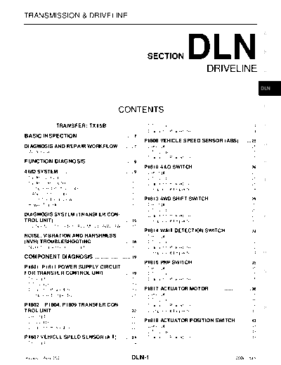
DLN


>> Download DLN documenatation <<

Text preview - extract from the document
TRANSMISSION & DRIVELINE

                                                                                                                                                                  A


                                                                                  SECTION                    DLN            DRIVELINE
                                                                                                                                                                  B


                                                                                                                                                                  C


                                                                                                                                                                  DLN


                                                                                                                                                                  E
                                                                 CONTENTS
                     TRANSFER: TX15B                                               DTC Logic ...............................................................24
                                                                                                                                                        .         F
                                                                                   Diagnosis Procedure ..............................................24 .
BASIC INSPECTION ................................... 7
                                                .
                                                                                 P1808 VEHICLE SPEED SENSOR (ABS) ....... 25
                                                                                                                                                                  G
DIAGNOSIS AND REPAIR WORKFLOW ......... 7
                                  .                                                Description ..............................................................25
                                                                                                                                                         .
  Work Flow ................................................................ 7
                                                                      .            DTC Logic ...............................................................25
                                                                                                                                                         .
                                                                                   Diagnosis Procedure ..............................................25  .
FUNCTION DIAGNOSIS .............................. 9
                                             .                                                                                                                    H
                                                                                 P1810 4 LO SWITCH ........................................ 26
4WD SYSTEM .................................................... 9
                                                          .                        Description ..............................................................26
                                                                                                                                                         .
  System Diagram ....................................................... 9
                                                                    .              DTC Logic ...............................................................26
                                                                                                                                                         .         I
  System Description ................................................ 10
                                                                    .              Diagnosis Procedure ..............................................26  .
  Component Parts Location ..................................... 12 .              Component Inspection ............................................28   .
  CAN Communication .............................................. 13
                                                                    .
  Cross-Sectional View ............................................. 13
                                                                    .            P1813 4WD SHIFT SWITCH ............................. 29                           J
  Power Transfer ....................................................... 13
                                                                    .              Description ..............................................................29
                                                                                                                                                         .
                                                                                   DTC Logic ...............................................................29
                                                                                                                                                         .
DIAGNOSIS SYSTEM (TRANSFER CON-                                                    Diagnosis Procedure ..............................................29  .        K
TROL UNIT) .......................................................15
                                                              .                    Component Inspection ............................................31   .
  CONSULT-III Function (ALL MODE AWD/4WD) .... 15
                                                                                 P1814 WAIT DETECTION SWITCH ................. 32
NOISE, VIBRATION AND HARSHNESS                                                     Description ..............................................................32
                                                                                                                                                         .        L
(NVH) TROUBLESHOOTING ...........................18
                                             .                                     DTC Logic ...............................................................32
                                                                                                                                                         .
  NVH Troubleshooting Chart ................................... 18
                                                           .                       Diagnosis Procedure ..............................................32  .
                                                                                   Component Inspection ............................................34   .        M
COMPONENT DIAGNOSIS ........................ 19
                                         .
                                                                                 P1816 PNP SWITCH ......................................... 35
P1801, P1811 POWER SUPPLY CIRCUIT                                                  Description ..............................................................35
                                                                                                                                                         .
FOR TRANSFER CONTROL UNIT ...................19
                                         .                                         DTC Logic ...............................................................35
                                                                                                                                                         .        N
  Description ............................................................. 19
                                                                       .           Diagnosis Procedure ..............................................35  .
  DTC Logic .............................................................. 19
                                                                       .
  Diagnosis Procedure .............................................. 19.         P1817 ACTUATOR MOTOR ............................. 36                            O
  Component Inspection ........................................... 21  .           Description ..............................................................36
                                                                                                                                                         .
                                                                                   DTC Logic ...............................................................36
                                                                                                                                                         .
P1802 


◦ Jabse Service Manual Search 2024 ◦ Jabse PravopisonTap.bg ◦ Other service manual resources online : FixyaeServiceinfo