Service Manuals, User Guides, Schematic Diagrams or docs for : . Car Manuals Nissan Xterra 2000-2004 Approved Nissan Xterra 2004 RFD

<< Back | Home

Most service manuals and schematics are PDF files, so You will need Adobre Acrobat Reader to view : Acrobat Download Some of the files are DjVu format. Readers and resources available here : DjVu Resources
For the compressed files, most common are zip and rar. Please, extract files with Your favorite compression software ( WinZip, WinRAR ... ) before viewing. If a document has multiple parts, You should download all, before extracting.
Good luck. Repair on Your own risk. Make sure You know what You are doing.


Image preview - the first page of the document
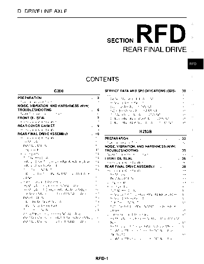
RFD


>> Download RFD documenatation <<

Text preview - extract from the document
D DRIVELINE/AXLE

                                                                                                                                                                  A


                                                                                                                                                                  B
                                                                                  SECTION
                                                                                                 REAR FINAL DRIVE                                                 C


                                                                                                                                                                  RFD


                                                                                                                                                                  E
                                                                CONTENTS
                                  C200                                          SERVICE DATA AND SPECIFICATIONS (SDS) ..... 30                           .        F
                                                                                 C200 ...................................................................... 30
                                                                                                                                                         .
PREPARATION .......................................................... 3
                                                                       .           GENERAL SPECIFICATIONS ............................ 30                .
 Special Service Tools .............................................. 3.           RING GEAR RUNOUT ....................................... 30           .        G
NOISE, VIBRATION, AND HARSHNESS (NVH)                                              SIDE GEAR ADJUSTMENT ............................... 30               .
TROUBLESHOOTING ............................................... 6      .           SIDE BEARING ADJUSTMENT ......................... 31                  .
 NVH Troubleshooting Chart .................................... 6      .           TOTAL PRELOAD ADJUSTMENT ..................... 31                     .
FRONT OIL SEAL ..................................................... 7 .                                                                                          H
                                                                                   DRIVE PINION HEIGHT ADJUSTMENT ........... 31                         .
 Removal and Installation ......................................... 7  .           DRIVE PINION PRELOAD ADJUSTMENT ........ 31                           .
REAR COVER GASKET ........................................... 9        .
 Removal and Installation ......................................... 9  .                                                                                           I
REAR FINAL DRIVE ASSEMBLY ........................... 10               .
                                                                                                                 H233B
 Removal and Installation ....................................... 10   .        PREPARATION ........................................................ 32  .
   REMOVAL .......................................................... 10
                                                                       .         Special Service Tools ............................................ 32   .        J
   INSTALLATION .................................................. 10  .        NOISE, VIBRATION, AND HARSHNESS (NVH)
 Components ...........................................................11
                                                                       .        TROUBLESHOOTING ............................................. 35         .
 Pre-Inspection ....................................................... 14
                                                                       .         NVH Troubleshooting Chart .................................. 35         .
   TOTAL PRELOAD .............................................. 14     .                                                                                          K
                                                                                FRONT OIL SEAL .................................................... 36   .
   RING GEAR-TO-DRIVE PINION BACKLASH ... 14                                     Removal and Installation ....................................... 36     .
   RING GEAR RUNOUT ....................................... 14         .        REAR FINAL DRIVE ASSEMBLY ........................... 38                 .
   TOOTH CONTACT ............................................. 14      .         Removal and Installation ....................................... 38     .        L
   SIDE GEAR-TO-PINION MATE GEAR BACK-                                             REMOVAL .......................................................... 38 .
   LASH .................................................................. 15
                                                                       .           INSTALLATION .................................................. 38    .
 Disassembly and Assembly .................................. 15        .         Components .......................................................... 39.        M
   REMOVAL OF DIFFERENTIAL CASE .............. 15                      .         Pre-Inspection ....................................................... 40
                                                                                                                                                         .
   REMOVAL OF DRIVE PINION ASSEMBLY ...... 16                          .           TOTAL PRELOAD .............................................. 40       .
   DISASSEMBLY OF DIFFERENTIAL CASE ....... 17                         .           RING GEAR TO DRIVE PINION BACKLASH .... 40                            .
   INSPECTION ..................................................... 18 .           RING GEAR RUNOUT ....................................... 40           .
   SIDE BEARING PRELOAD ............................... 19             .           TOOTH CONTACT ............................................. 41        .
   PINION GEAR HEIGHT ..................................... 21         .           SIDE GEAR TO PINION MATE GEAR BACK-
   TOOTH CONTACT ............................................. 24      .           LASH .................................................................. 41
                                                                                                                                                         .
   ASSEMBLY OF DIFFERENTIAL CASE ............. 25                      .         Disassembly and Assembly ................................... 41         .
   INSTALLATION OF DRIVE PINION ASSEMBLY 26                            ...         REMOVAL OF DIFFERENTIAL CASE ASSEM-
   INSTALLATION OF DIFFERENTIAL CASE ....... 28                        .           BLY ..................................................................... 41
                                                                                                                                                         .
                                                                                   REMOVAL OF DRIVE PINION ASSEMBLY ....... 42                           .
                                                                                   DISASSEMBLY OF DIFFERENTIAL CASE
                                                                                   (NON LSD) ......................................................... 44.
                                                                                   DISASSEMBLY OF DIFFERENTIAL CASE


                                                                         RFD-1
(WITH LSD) ........................................................ 45
                                                                     .        SERVICE DATA AND SPECIFICATIONS (SDS) .....62                    .
INSPECTION ...................................................... 47 .         General Specifications ...........................................62
                                                                                                                                               .
ADJUSTMENT OF DIFFERENTIAL CASE                                                  2WD MODEL ......................................................62
                                                                                                                                               .
(WITH LSD) ........................................................ 49
                                                                     .           4WD MODEL ......................................................62
                                                                                                                                               .
PINION GEAR HEIGHT ..................................... 50          .         Ring Gear Runout ..................................................62
                                                                                                                                               .
TOOTH CONTACT ............................................. 54       .         Side Gear Adjustment ............................................62
                                                                                                                                               .
ASSEMBLY OF DIFFERENTIAL CASE (NON                                             Differential Torque Adjustment (LSD Models) ........62          .
LSD) ................................................................... 55
                                                                     .         Total Preload Adjustment .......................................63
                                                                                                                                               .
ASSEMBLY OF DIFFERENTIAL CASE (WITH                                            Drive Pinion Height Adjustment .............................63  .
LSD) ................................................................... 56
                                                                     .         Drive Pinion Preload Adjustment ...........................64   .
INSTALLATION OF DRIVE PINION ASSEMBLY 58                             ...
INSTALLATION OF DIFFERENTIAL CASE ....... 60                         .


                                                                       RFD-2
                                                       PREPARATION
                                                                                                                               [C200]
PREPARATION                                                                                                                   PFP:00002
                                                                                                                                              A
Special Service Tools                                                                                                              EDS000TK

The actual shapes of Kent-Moore tools may differ from those of special service tools illustrated here.
  Tool number
                                                                                                                                              B
  (Kent-Moore No.)                                                                       Description
  Tool name
  ST3127S000                                                                             Measuring pinion bearing preload and total
  (See J25765-A)                                                                         preload                                              C
  Preload gauge
  1 GG91030000
  (J-25765)
  Torque wrench
                                                                                                                                              RFD
  2 HT62940000
  (      --      )
  Socket adapter                                                                                                                              E
  3 HT62900000                                                           NT124

  (      --      )
  Socket adapter
  KV38108300                                                                             Removing and installing propeller shaft lock         F
  (J-44195)                                                                              nut and drive pinion lock nut
  Companion flange wrench
                                                                                                                                              G


                                                                         NT771
                                                                                                                                              H
  ST3090S000                                                                             Removing and installing drive pinion rear in-
  (       --       )                                                                     ner cone
  Drive pinion rear inner race puller set                                                a: 79 mm (3.11 in) dia.
  1 ST30031000                                                                           b: 45 mm (1.77 in) dia.                               I
  (J-22912-01)                                                                           c: 35 mm (1.38 in) dia.
  Puller
  2 ST30901000
                                                                                                                                              J
  (J-26010-01)
                                                                         NT527
  Base
  ST3306S001                                                                             Removing and installing differential side bear-
  Differential side bearing puller set                                                   ing inner cone                                       K
  1 ST33051001                                                                           a: 28.5 mm (1.122 in) dia.
  (J-22888-20)                                                                           b: 38 mm (1.50 in) dia.
  Body
                                                                                                                                              L
  2 ST33061000
  (J8107-2)
  Adapter                                                                NT072


  ST33230000                                                                             Installing side bearing inner cone                   M
  (J-25805-01)                                                                           a: 51 mm (2.01 in) dia.
  Differential side bearing drift                                                        b: 41 mm (1.61 in) dia.
                                                                                         c: 28.5 mm (1.122 in) dia.


                                                                         NT085


  ST33081000                                                                             Installing side bearing inner cone and remov-
  (      --        )                                                                     ing and installing differential case couple
  Side bearing puller adapter                                                            bolts


◦ Jabse Service Manual Search 2024 ◦ Jabse PravopisonTap.bg ◦ Other service manual resources online : FixyaeServiceinfo