Service Manuals, User Guides, Schematic Diagrams or docs for : . Car Manuals Nissan Xterra 2000-2004 Approved Nissan Xterra 2003 FAX

<< Back | Home

Most service manuals and schematics are PDF files, so You will need Adobre Acrobat Reader to view : Acrobat Download Some of the files are DjVu format. Readers and resources available here : DjVu Resources
For the compressed files, most common are zip and rar. Please, extract files with Your favorite compression software ( WinZip, WinRAR ... ) before viewing. If a document has multiple parts, You should download all, before extracting.
Good luck. Repair on Your own risk. Make sure You know what You are doing.


Image preview - the first page of the document
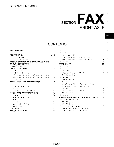
FAX


>> Download FAX documenatation <<

Text preview - extract from the document
D DRIVELINE/AXLE

                                                                                                                                                                 A


                                                                                                                                                                 B
                                                                                    SECTION
                                                                                                                    FRONT AXLE                                   C


                                                                                                                                                                 FAX


                                                                                                                                                                 E
                                                                CONTENTS
PRECAUTIONS ......................................................... 2.         Removal ................................................................ 17
                                                                                                                                                        .        F
 Precautions ............................................................. 2
                                                                       .         Inspection .............................................................. 18
                                                                                                                                                        .
PREPARATION .......................................................... 3
                                                                       .           KNUCKLE SPINDLE .......................................... 18        .
 Special Service Tools .............................................. 3.           BEARING SPACER (2WD MODELS) ................ 18                      .        G
 Commercial Service Tools ....................................... 3    .           NEEDLE BEARING (4WD MODELS) ................ 18                      .
NOISE VIBRATION AND HARSHNESS (NVH)                                              Installation ............................................................. 18
                                                                                                                                                        .
TROUBLESHOOTING ............................................... 4      .        DRIVE SHAFT .......................................................... 20
                                                                                                                                                        .
                                                                                                                                                                 H
 NVH Troubleshooting Chart .................................... 4      .         Components .......................................................... 20
                                                                                                                                                        .
ON-VEHICLE SERVICE ............................................ 5      .         Removal ................................................................ 20
                                                                                                                                                        .
 Front Axle Parts ...................................................... 5
                                                                       .         Disassembly .......................................................... 21
                                                                                                                                                        .
 Front Wheel Bearing ............................................... 5 .           FINAL DRIVE SIDE (TS82F) .............................. 21           .         I
   PRELOAD ADJUSTMENT (2WD MODELS) ....... 5                           .           WHEEL SIDE (ZF100) ....................................... 22        .
   PRELOAD ADJUSTMENT (4WD MODELS) ....... 6                           .         Inspection .............................................................. 22
                                                                                                                                                        .
 Drive Shaft .............................................................. 8
                                                                       .           DRIVE SHAFT .................................................... 22  .         J
AUTO-LOCK FREE-RUNNING HUB ........................ 9                  .           BOOT ................................................................. 22
                                                                                                                                                        .
 Description .............................................................. 9
                                                                       .           JOINT ASSEMBLY (FINAL DRIVE SIDE) .......... 22                      .
 Removal and Installation ......................................... 9  .           JOINT ASSEMBLY (WHEEL SIDE) ................... 22                   .
                                                                                                                                                                 K
 Inspection .............................................................. 10
                                                                       .         Assembly ............................................................... 23
                                                                                                                                                        .
 Trouble Diagnosis For Noise ................................. 10      .           FINAL DRIVE SIDE (TS82F) .............................. 23           .
WHEEL HUB AND ROTOR DISC ........................... 12                .           WHEEL SIDE (ZF100) ....................................... 24        .
 Components .......................................................... 12
                                                                       .         Installation ............................................................. 25
                                                                                                                                                        .         L
 Removal and Installation ....................................... 14   .        SERVICE DATA AND SPECIFICATIONS (SDS) ..... 27                          .
 Disassembly .......................................................... 15
                                                                       .         Wheel Bearing (Front) ........................................... 27   .
 Inspection .............................................................. 15
                                                                       .           2WD MODELS ................................................... 27    .        M
   WHEEL BEARINGS ........................................... 15       .           4WD MODELS ................................................... 27    .
   WHEEL HUB ...................................................... 15 .         Drive Shaft (4WD models) ..................................... 27      .
 Assembly ............................................................... 15
                                                                       .           DRIVE SHAFT AXIAL END PLAY ...................... 27                 .
KNUCKLE SPINDLE ............................................... 17     .           DRIVE SHAFT END SNAP RING ...................... 28                  .


                                                                         FAX-1
                                       PRECAUTIONS

PRECAUTIONS                                                                              PFP:00001

Precautions                                                                                 EDS000P1


q  When installing rubber parts, final tightening must be car-
   ried out under unladen condition* with tires on ground.
   *: Fuel, radiator coolant and engine oil full. Spare tire, jack,
   hand tools and mats in designated positions.
q  Use flare nut wrench when removing and installing brake
   tubes.
q  After installing removed suspension parts, check wheel
   alignment and adjust if necessary.
q  Always torque brake lines when installing.
CAUTION:                                                                                  SBR686C
q  The ZF100 (wheel side) type joint assembly has two types
   of boot material; one is made of rubber and the other is made of plastic.
q  Do not disassemble the joint assembly with the plastic boot. If the boot or joint is damaged,
   replace the drive shaft assembly.


                                            FAX-2
                                                       PREPARATION

PREPARATION                                                                                                                    PFP:00002
                                                                                                                                              A
Special Service Tools                                                                                                              EDS000P2

The actual shapes of Kent-Moore tools may differ from those of special service tools illustrated here.
  Tool number
                                                                                                                                              B
  (Kent-Moore No.)                                                                                        Description
  Tool name
  ST29020001                                                                             Removing ball joint for knuckle spindle
  (J24319-01)                                                                            a: 34 mm (1.34 in)                                   C
  Gear arm puller                                                                        b: 6.5 mm (0.256 in)
                                                                                         c: 61.5 mm (2.421 in)
                                                                                                                                              FAX

                                                                         NT694


  HT72520000                                                                             Removing tie-rod outer end and lower ball            E
  (J25730-B)                                                                             joint
  Ball joint remover                                                                     a: 33 mm (1.30 in)
                                                                                         b: 50 mm (1.97 in)
                                                                                         r: R11.5 mm (0.453 in)                               F


                                                                         NT546
                                                                                                                                              G
  KV401021S0                                                                             Installing wheel bearing outer race
  (      --        )
  Bearing race drift
                                                                                                                                              H


                                                                         NT153
                                                                                                                                               I
  KV40105400                                                                             Removing and installing wheel bearing lock
  (J36001)                                                                               nut
  Wheel bearing lock nut wrench                                                          (4WD models only)                                     J


                                                                                                                                              K
                                                                         NT154


Commercial Service Tools                                                                                                           EDS000P3
                                                                                                                                               L
  Tool name                                                                                               Description
  1 Flare nut crowfoot                                                                   Removing and installing each brake piping
  2 Torque wrench                                                                        a: 10 mm (0.39 in)                                   M


                                                                         S-NT360


                                                               FAX-3
                                                                   Symptom


◦ Jabse Service Manual Search 2024 ◦ Jabse PravopisonTap.bg ◦ Other service manual resources online : FixyaeServiceinfo