Service Manuals, User Guides, Schematic Diagrams or docs for : . Car Manuals Subaru Forester 1999-2004 Approved Subaru Forester 1999-2000 AUTOMATIC TRANSMISSION MSA5T0128A34681

<< Back | Home

Most service manuals and schematics are PDF files, so You will need Adobre Acrobat Reader to view : Acrobat Download Some of the files are DjVu format. Readers and resources available here : DjVu Resources
For the compressed files, most common are zip and rar. Please, extract files with Your favorite compression software ( WinZip, WinRAR ... ) before viewing. If a document has multiple parts, You should download all, before extracting.
Good luck. Repair on Your own risk. Make sure You know what You are doing.


Image preview - the first page of the document
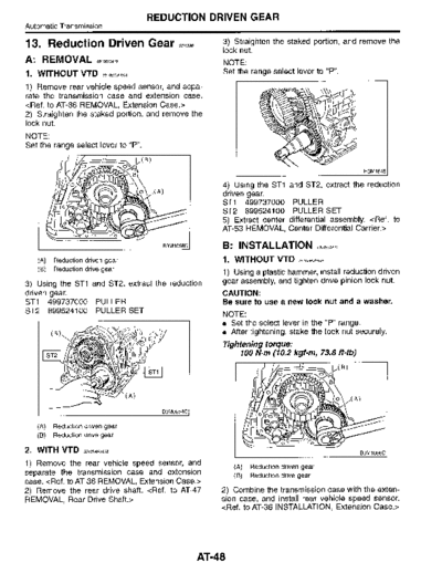
MSA5T0128A34681


>> Download MSA5T0128A34681 documenatation <<

Text preview - extract from the document
                                                  REDUCTION DRIVEN GEAR
Automatic Transmission

13 . Reduction Driven Gear                                 S5f0590
                                                                        3) Straighten the staked portion, and remove the
                                                                        lock nut.
A : REMOVAL S5,o59oA,8                                                  NOTE :
1 . WITHOUT VTD              S510590A1807
                                                                        Set the range select lever to "P".
1) Remove rear vehicle speed sensor, and sepa-
rate the transmission case and extension case .

2) Straighten the staked portion, and remove the
lock nut.
NOTE:
Set the range select lever to "P".
                                                (B)
                                            a
                0                                                       4) Using the ST1               and ST2, extract the reduction
                                                o\ .(A)                 driven gear.
           0                                                            ST1 499737000                   PULLER
                                                                        ST2 899524100                   PULLER SET
            0                                                           5) Extract center              differential assembly. 

                                                       83M1058C         B : INSTALLATION                            5510590A77


   (A)   Reduction driven gear                                          1 . WITHOUT VTD                   5510590A1101

   (B)   Reduction drive gear
                                                                        1) Using a plastic hammer, install reduction driven
3) Using the ST1 and ST2, extract the reduction                         gear assembly, and tighten drive pinion lock nut.
driven gear.                                                            CAUTION :
ST1 499737000 PULLER                                                    Be sure to use a new lock nut and a washer.
ST2 899524100 PULLER SET                                                NOTE :
                                                                        " Set the select lever in the "P" range.
                                                                          After tightening, stake the lock nut securely.
                                                                        Tightening torque:
                                                                            100 N~m (10.2 kgf-m, 73.8 ft-Ib)
                                                                                                                -          ~ ( B)
                                                                                                                     0
                                                                                                         ---         , a
                                                                                         o       ~
                                                                                                                            o       (A)
                                                                                         O


   (A)   Reduction driven gear
                                                                                             o
                                                                                     0
   (B)   Reduction drive gear
                                                                                                 o ~           ro

2. WITH VTD         5510590A1802
                                                                                                                                          B3M1058C

1) Remove the rear vehicle speed sensor, and                                (A)   Reduction driven gear
separate the transmission case and extension                                (B)   Reduction drive gear
case . 
2) Remove the rear drive shaft.                                              sion case, and install rear vehicle speed sensor.


                                                                     AT48
                                   REDUCTION DRIVEN GEAR
                                                                                                 Automatic Transmission

2. WITH VTD S5,oSWA o2                                    2) Using ST, remove ball bearing from reduction
                                                          driven gear.
 1) Using a plastic hammer, install reduction driven
                                                          ST 498077600 REMOVER
gear assembly.
2) Using a plastic hammer, install center differen-
tial .
3) Tighten drive pinion lock nut.
CAUTION:
Be sure to use a new lock nut and a washer.
NOTE :
" Set the range select lever in the "P" range .
  After tightening, stake the lock nut securely.
Tightening torque:
    100 N~m (10.2 kgf-m, 73.8 ft-Ib)
                                                             (A)    Ball bearing

                                                          3) Remove snap rings from reduction driven gear .
                                                          (2 .5 L US model and 3.0 L model)

                                                          D : ASSEMBLY             5570590A02


                                                          1) Install snap rings to reduction driven gear. (2.5
                                                          L US model and 3.0 L model)
                                                          2) Using a press, install ball bearing to reduction
                                                          driven gear.


4) Insert the rear drive shaft assembly. 
5) Combine the transmission case with the exten-
                                                                                                      A)
sion case, and install rear vehicle speed sensor.


C : DISASSEMBLY
1) Remove snap ring from reduction driven gear.
                                                                                                           B3M1128B

                                                             (A)   Ball bearing

                                                       3) Install snap ring to reduction driven gear.

           (A)


                                       B3M 11258

   (A)   Snap ring

                                                                                                           83M1125B~

                                                            (A)    Snap ring

                                                       E : INSPECTION               5510590A10


                                                       Check ball bearing and gear for dents or damage.


                                                   AT49


◦ Jabse Service Manual Search 2024 ◦ Jabse PravopisonTap.bg ◦ Other service manual resources online : FixyaeServiceinfo