Service Manuals, User Guides, Schematic Diagrams or docs for : . Car Manuals Subaru Forester 1999-2004 Approved Subaru Forester 1999-2000 ENGINE SECTION Engine Cooling System MSA5T0122A27596

<< Back | Home

Most service manuals and schematics are PDF files, so You will need Adobre Acrobat Reader to view : Acrobat Download Some of the files are DjVu format. Readers and resources available here : DjVu Resources
For the compressed files, most common are zip and rar. Please, extract files with Your favorite compression software ( WinZip, WinRAR ... ) before viewing. If a document has multiple parts, You should download all, before extracting.
Good luck. Repair on Your own risk. Make sure You know what You are doing.


Image preview - the first page of the document
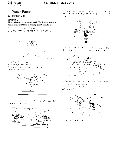
MSA5T0122A27596


>> Download MSA5T0122A27596 documenatation <<

Text preview - extract from the document
2-5   [W1A0]                          SERVICE PROCEDURE
1. Water Pump


1. Water Pump                                         7) Detach ATF cooler hose attached to a clip
                                                      under the radiator main fan shroud. (AT vehicles
A: REMOVAL                                            only)
WARNING:
The radiator is pressurized. Wait until engine
cools down before working on the radiator.
1) Set the vehicle on the lift.
2) Disconnect ground cable from the battery.


                                                                                             H2M3592

                                                      8) Remove bolt which installs water by-pass pipe
                                                      of oil cooler onto oil pump. (AT vehicles only)


                                       G6M0095

3) Lift-up the vehicle.
4) Remove under cover.
5) Drain engine coolant completely.


                                                                                             S2M0027

                                                      9) Disconnect radiator outlet hose (A) and heater
                                                      hose (B) from water pump.
                                                      10) Disconnect water by-pass hose (C). (AT
                                                      vehicles only)


                                       B2M0015

6) Disconnect connectors from radiator main fan
and sub fan motors.


                                                                                            S2M0015A

                                                      11) Lower the vehicle.


                                       S2M0893


                                                  6
                                  SERVICE PROCEDURE                                      [W1A0] 2-5
                                                                                        1. Water Pump


12) Disconnect over flow hose.                        17) Remove automatic belt tension adjuster.


                                     S2M0930                                                 H2M2375

13) Remove reservoir tank.                            18) Remove belt idler No. 2.


                                     S2M0931                                                 S2M0024

14) Remove radiator main fan and sub fan assem-       19) Remove camshaft position sensor.
blies.  and 
[W6A0].>


                                                                                             B2M2038
                                     S2M0929
                                                      20) Remove left-hand camshaft sprocket by using
15) Remove V-belts.                                   ST.
                                 ST 499207100 CAMSHAFT SPROCKET
                                                                       WRENCH


                                     G2M0286
                                                                                           B2M2039A
16) Remove timing belt.


                                                  7
2-5   [W1B0]                       SERVICE PROCEDURE
1. Water Pump


21) Remove left-hand belt cover No. 2.                 3) Using a dial gauge, measure impeller runout in
                                                       thrust direction while rotating the pulley.
                                                       "Thrust" runout limit:
                                                           0.5 mm (0.020 in)


                                         B2M2040

22) Remove tensioner bracket.
                                                                                                 G2M0211

                                                       4) Check clearance between impeller and pump
                                                       case.
                                                       Clearance between impeller and pump case:
                                                         Standard
                                                           0.5 -- 0.7 mm (0.020 -- 0.028 in)
                                                         Limit
                                                           1.0 mm (0.039 in)
                                         H2M2380

23) Remove tensioner bracket.
24) Disconnect heater hose from water pump.
25) Remove water pump.


                                                                                                 G2M0212

                                                       5) After water pump installation, check pulley shaft
                                                       for engine coolant leaks. If leaks are noted, replace
                                                       water pump assembly.
                                         S2M1829


B: INSPECTION
1) Check water pump bearing for smooth rotation.
2) Check water pump pulley for abnormalities.


                                                   8
                                         SERVICE PROCEDURE                                    [W1C0] 2-5
                                                                                             1. Water Pump


C: INSTALLATION                                           4) Install left-hand camshaft sprockets by using
                                                          ST.
1) Install water pump onto left-hand cylinder head.       ST 4992707100 CAMSHAFT SPROCKET
CAUTION:                                                                       WRENCH


◦ Jabse Service Manual Search 2024 ◦ Jabse PravopisonTap.bg ◦ Other service manual resources online : FixyaeServiceinfo