Service Manuals, User Guides, Schematic Diagrams or docs for : . Car Manuals Subaru Forester 1999-2004 Approved Subaru Forester 2004 4 - Chassis ABS (Diagnostics) Diagnostics Procedure with Diagnostic Trouble Code (DTC

<< Back | Home

Most service manuals and schematics are PDF files, so You will need Adobre Acrobat Reader to view : Acrobat Download Some of the files are DjVu format. Readers and resources available here : DjVu Resources
For the compressed files, most common are zip and rar. Please, extract files with Your favorite compression software ( WinZip, WinRAR ... ) before viewing. If a document has multiple parts, You should download all, before extracting.
Good luck. Repair on Your own risk. Make sure You know what You are doing.


Image preview - the first page of the document
Diagnostics Procedure with Diagnostic Trouble Code (DTC


>> Download Diagnostics Procedure with Diagnostic Trouble Code (DTC documenatation <<

Text preview - extract from the document
    DIAGNOSTICS PROCEDURE WITH DIAGNOSTIC TROUBLE CODE (DTC)
ABS (DIAGNOSTICS)

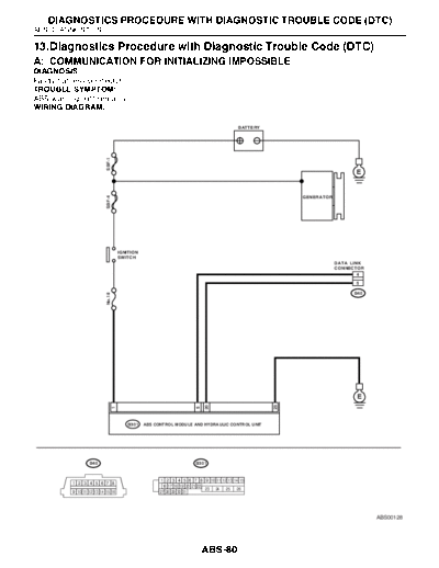
13.Diagnostics Procedure with Diagnostic Trouble Code (DTC)
A: COMMUNICATION FOR INITIALIZING IMPOSSIBLE
DIAGNOSIS:
Faulty harness connector
TROUBLE SYMPTOM:
ABS warning light remains on.
WIRING DIAGRAM:

                                                                                        BATTERY
                           SBF-1


                                                                                                                         E


                                                                                                       GENERATOR
                           SBF-4


                                       IGNITION
                                       SWITCH
                                                                                                                   DATA LINK
                                                                                                                   CONNECTOR
                                                                                                                           4

                                                                                                                         5

                                                                                                                         B40
                           No.18


                                                                                                                          E
                                                                           20


                                                                                                  23
                                   1


                                                                       5


                                          B301    ABS CONTROL MODULE AND HYDRAULIC CONTROL UNIT


                  B40                                                  B301


                                                        1 2 3 4 5 6 7 8 9 10 11 12 13 14 15
          1 2 3 4 5 6 7 8
                                                         16 17 18 19 20 21 22
                                                                              23 24 25 26
          9 10 11 12 13 14 15 16                        27 28 29 30 31


                                                                                                                               ABS00128


                                                                           ABS-80
    DIAGNOSTICS PROCEDURE WITH DIAGNOSTIC TROUBLE CODE (DTC)
                                                                                                       ABS (DIAGNOSTICS)

                  Step                                            Check                       Yes                 No
1     CHECK IGNITION SWITCH.                        Is the ignition switch turned to   Go to step 2.      Turn the ignition
                                                    ON?                                                   switch to ON, and
                                                                                                          select ABS mode
                                                                                                          using SUBARU
                                                                                                          select monitor.
2     CHECK BATTERY.                                Is the voltage more than 11 V? Go to step 3.          Charge or replace
      1) Turn the ignition switch to OFF.                                                                 the battery.
      2) Measure the battery voltage.
3     CHECK BATTERY TERMINAL.                       Is there poor contact at battery Repair or tighten    Go to step 4.
                                                    terminal?                        the battery termi-
                                                                                     nal.
4     CHECK COMMUNICATION OF SELECT                 Are the name and year of sys- Go to step 7.           Go to step 5.
      MONITOR.                                      tem displayed on select moni-
      1) Turn the ignition switch to ON.            tor?
      2) Using the select monitor, check whether
      communication to other system can be exe-
      cuted normally.
5     CHECK COMMUNICATION OF SELECT                 Are the name and year of sys- Go to step 7.           Go to step 6.
      MONITOR.                                      tem displayed on select moni-
      1) Turn the ignition switch to OFF.           tor?
      2) Disconnect the ABSCM&H/U connector.
      3) Turn the ignition switch to ON.
      4) Check whether communication to other
      systems can be executed normally.
6     CHECK HARNESS CONNECTOR BETWEEN               Is the resistance more than 1      Go to step 7.      Repair the har-
      EACH CONTROL MODULE AND DATA LINK             M?                                                    ness and connec-
      CONNECTOR.                                                                                          tor between each
      1) Turn the ignition switch to OFF.                                                                 control module
      2) Disconnect the ABSCM&H/U, ECM and                                                                and data link con-
      TCM connectors.                                                                                     nector.
      3) Measure the resistance between data link
      connector and chassis ground.
       Connector & terminal
         (B40) No. 5 -- Chassis ground:
         (B40) No. 4 -- Chassis ground:
7     CHECK OUTPUT SIGNAL FOR ABSCM&                Is the voltage less than 1 V?      Go to step 8.      Repair the har-
      H/U.                                                                                                ness and connec-
      1) Turn the ignition switch to ON.                                                                  tor between each
      2) Measure the voltage between ABSCM&H/                                                             control module
      U and chassis ground.                                                                               and data link con-
       Connector & terminal                                                                               nector.
         (B40) No. 5 (+) -- Chassis ground (-):
         (B40) No. 4 (+) -- Chassis ground (-):
8     CHECK HARNESS/CONNECTOR BETWEEN               Is the resistance less than 0.5 Repair the har-   Go to step 9.
      ABSCM&H/U AND DATA LINK CONNEC-               ?                               ness and connec-
      TOR.                                                                          tor between
      Measure the resistance between ABSCM&H/U                                      ABSCM&H/U and
      connector and data link connector.                                            data link connec-
       Connector & terminal                                                         tor.
         (B301) No. 20 -- (B40) No. 5:
         (B301) No. 5 -- (B40) No. 4:
9     CHECK INSTALLATION OF ABSCM&H/U               Is the ABSCM&H/U connector Go to step 10.             Insert the
      CONNECTOR.                                    inserted into ABSCM&H/U until                         ABSCM&H/U con-
      Turn the ignition switch to OFF.              the clamp locks onto it?                              nector into
                                                                                                          ABSCM&H/U.


                                                    ABS-81
     DIAGNOSTICS PROCEDURE WITH DIAGNOSTIC TROUBLE CODE (DTC)
ABS (DIAGNOSTICS)

                       Step                                        Check                    Yes                    No
10     CHECK POWER SUPPLY CIRCUIT.                    Is the voltage more than 10 V? Go to step 11.      Repair the open
       1) Turn the ignition switch to ON (engine                                                         circuit in harness
       OFF).                                                                                             between
       2) Measure the ignition power supply voltage                                                      ABSCM&H/U and
       between ABSCM&H/U connector and chassis                                                           battery.
       ground.
        Connector & terminal
          (B301) No. 1 (+) -- Chassis ground (-):
11     CHECK HARNESS CONNECTOR BETWEEN                Is the resistance less than 1   Go to step 12.     Repair the open
       ABSCM&H/U AND CHASSIS GROUND.                  ?                                                  circuit in harness
       1) Turn the ignition switch to OFF.                                                               between
       2) Disconnect the connector from ABSCM&H/                                                         ABSCM&H/U and
       U and transmission.                                                                               inhibitor side con-
       3) Measure the resistance of harness                                                              nector, and poor
       between ABSCM&H/U and chassis ground.                                                             contact in cou-
        Connector & terminal                                                                             pling connector.
          (B301) No. 23 -- Chassis ground:
12     CHECK POOR CONTACT IN CONNECTORS.              Is there poor contact in control Repair the con-   Replace the
                                                      module power supply, ground nector.                ABSCM&H/U.
                                                      line and data link connector?                      


                                                      ABS-82
   DIAGNOSTICS PROCEDURE WITH DIAGNOSTIC TROUBLE CODE (DTC)
                                                                               ABS (DIAGNOSTICS)

B: NO TROUBLE CODE
DIAGNOSIS:
ABS warning light circuit is shorted.
TROUBLE SYMPTOM:


◦ Jabse Service Manual Search 2024 ◦ Jabse PravopisonTap.bg ◦ Other service manual resources online : FixyaeServiceinfo