Service Manuals, User Guides, Schematic Diagrams or docs for : . Car Manuals Subaru Forester 1999-2004 Approved Subaru Forester 2004 5 - Body HVAC SYSTEM (AUTO AC) (DIAGNOSTICS) Self-diagnosis

<< Back | Home

Most service manuals and schematics are PDF files, so You will need Adobre Acrobat Reader to view : Acrobat Download Some of the files are DjVu format. Readers and resources available here : DjVu Resources
For the compressed files, most common are zip and rar. Please, extract files with Your favorite compression software ( WinZip, WinRAR ... ) before viewing. If a document has multiple parts, You should download all, before extracting.
Good luck. Repair on Your own risk. Make sure You know what You are doing.


Image preview - the first page of the document
Self-diagnosis


>> Download Self-diagnosis documenatation <<

Text preview - extract from the document
                                                           SELF-DIAGNOSIS
HVAC SYSTEM (AUTO A/C) (DIAGNOSTICS)

5. Self-diagnosis
A: OPERATION
               (3)                                           (4)                                                           (5)


        (2)                                                                                                                      (7)


                             (1)                               (9)                                               (6)
                                                                                    (8)
                                                                                                                                       AC-00100

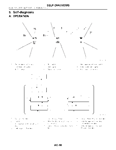
 (1)   Temperature control dial                     (4)    A/C switch                            (7)      Rear window defogger switch
 (2)   OFF/BRIGHT switch                            (5)    DEF switch                            (8)      FRESH/RECIRC switch
 (3)   AUTO switch                                  (6)    Mode control dial                     (9)      Fan speed control dial


                                                                                                                 :   (2)
                                           (1)


                     (3)
                                                   OFF
               DEF    + A   /C
                                                                             (4)


                                           (5)


                                     (6)            AUTO
                                                                                                FRESH / RECIRC
                                                            FRESH / RECIRC
                            A/C
                                           (7)                                                     (9)
                                                                                   A/C
                                   AUTO                                                           AUTO
                                                    A/C                        FRESH / RECIRC


                                           (8)                                                     (10)
                                                            FRESH / RECIRC         A/C
                                            AUTO                                                AUTO

                                                                                                                                       AC-00242

 (1)   Normal Operation                             (5)    LED Display Check                     (8)      Sensor Check (Phased Operation)
 (2)   Switch                                       (6)    After the LED display for approx.     (9)      Output Equipment Operation
 (3)   Turn ignition switch on with press-                 20 seconds.                                    (Sequential Operation)
       ing                                          (7)    Sensor Check (Sequential Opera-      (10)      Output Equipment Operation
 (4)   Self-diagnosis Function                             tion)                                          (Phased Operation)


                                                                     AC-10
                                            SELF-DIAGNOSIS
                                                                          HVAC SYSTEM (AUTO A/C) (DIAGNOSTICS)

                    Step                                   Check                             Yes                    No
1   SELECT CONTROL PANEL TO SELF-DIAG- Does the self-diagnosis func-                  Go to step 2.        
2   CHECK LED ILLUMINATION.                         Do all LED blink?                 Go to step 3.        Go to step 5.
    Make sure that three LED blink in turn on con-
    trol panel. (5 patterns are repeated 2 times.)
3   CHECK SENSORS MALFUNCTION.                      Does each DEF, MODE and           Go to step 4.        Confirm the com-
    1) After the LED check completed or AUTO        fan speed LED turn off?                                bination of illumi-
    switch pressed, the A/C switch LED illumi-                                                             nating LEDs by
    nates, and then the sensor check is started.                                                           using Sensor
    2) Check the input signal of each sensor in                                                            Check Table, and
    turn. If there are any trouble for each sensor,                                                        identify the mal-
    DEF, MODE and fan speed LEDs blinks. Also                                                              functioning sensor
    check for each sensor is possible respectively                                                         before repairing.
    every time AUTO switch is pressed. (At this                                                                                                                                             TION, Self-diagno-
    3) If there is no trouble, DEF, MODE and fan                                                           sis.>
    speed LEDs are turned off.
    NOTE:
    Rear window defogger LED illuminates in case
    of stored malfunction but does not illuminate in
    case of present malfunction.
4   CHECK OPERATION OF EACH ACTUATOR,                  Does each actuator, compres-   Press the OFF        Refer to each
    COMPRESSOR AND FAN MOTOR.                          sor and fan motor operate      switch or turn the   diagnostics chart
    1) Press the FRESH/RECIRC switch.                  according to operating mode    ignition switch to   for actuator, com-
    (FRESH/RECIRC switch LED illuminates at            table?                         OFF and finish the   pressor and fan
    this time.)                                                                       self-diagnosis       motor, and repair
    2) Refer to OPERATING MODE TABLE to                                               function.            the malfunctioning
    check the operation of each actuator, compres-                                                         part as necessary.
    sor and fan motor. 
    Also check for each step is possible respec-
    tively every time AUTO switch pressed. (At this
    time, the AUTO switch LED illuminates.)
5   CHECK POOR CONTACT.                                Is there a poor contact in con- Repair the con-     Replace the A/C
    Check the A/C control module connector for         nector?                         nector.             control module.
    poor contact.


                                                        AC-11
                                                  SELF-DIAGNOSIS
HVAC SYSTEM (AUTO A/C) (DIAGNOSTICS)

1. SENSOR CHECK TABLE
NOTE:
When the sunload sensor is checked indoors or in the shade, open circuit might be indicated. Always check
the sunload sensor at a place where sun shines directly on it.
                                                                                                        Present     Stored
 Diag-                                           Open circuit               Short circuit
                                                                                                       malfunction malfunction
 nostic             Checked sensor
 steps                                                   MODE/FAN                     MODE/FAN
                                          DEF LED                    DEF LED                           REAR DEFOGGER LED
                                                            LED                          LED
                                                           VENT                         VENT
   1       In-vehicle sensor                                LED                          LED
                                                           blinks                       blinks
                                                         BI-LEVEL                     BI-LEVEL
   2       Ambient sensor                                   LED                          LED
                                                           blinks                       blinks
                                                           HEAT                         HEAT
   3       Evaporator sensor                                LED                          LED
                                                           blinks                       blinks
                                           Turn off      DEF/HEAT    Illuminate       DEF/HEAT          Turn off    Illuminate
   4       Sunload sensor*1                                 LED                          LED
                                                           blinks                       blinks
                                                         Fan speed                    Fan speed
                                                             1st                          1st
   5       Air mix door actuator P.B.R.
                                                            LED                          LED
                                                           blinks                       blinks
                                                         Fan speed                    Fan speed
           Combination meter commu-                         2nd                          2nd
   6
           nication (Ambient sensor)                        LED                          LED
                                                           blinks                       blinks
           When all parts are in good
                                                                           Turn off
           condition

*1: Only present malfunction is indicated for open circuit of sunload sensor. (However, stored malfunction
can be indicated for short circuit of sunload sensor.)
2. OPERATING MODE TABLE
             Step                   1          2          3        4           5               6            7            8
                                 VENT     BI-LEVEL             DEF/HEAT    Fan dial         Fan dial     Fan dial    Fan dial
       Illuminating LED                               HEAT LED
                                  LED       VENT                  LED      1st LED          2nd LED      3rd LED     4th LED
           Fan dial                LO         LO          ML       ML        ML               MH           MH           HI
       Mode actuator             VENT       VENT        VENT   BI-LEVEL     HEAT             HEAT       DEF/HEAT       DEF
       Intake actuator          FRESH     RECIRC       RECIRC   FRESH      FRESH            FRESH        FRESH       FRESH
                                 FULL       FULL        FULL
                                                                MEDIUM     MEDIUM       FULL HOT        FULL HOT    FULL HOT
 Air mix door actuator (%)      COOL       COOL         COOL
                                                                 (50%)      (50%)        (100%)          (100%)      (100%)
                                 (0%)        (0%)        (0%)
          Compressor              OFF         ON          ON      ON          ON              ON           ON          ON


                                                           AC-12


◦ Jabse Service Manual Search 2024 ◦ Jabse PravopisonTap.bg ◦ Other service manual resources online : FixyaeServiceinfo