Service Manuals, User Guides, Schematic Diagrams or docs for : . Car Manuals Subaru Legacy 2000-2003 Approved Subaru Legacy 2000 2000 Service Manual ELECTRICAL SECTION Body Electrical System MSA5TCD00L16052
<< Back | HomeMost service manuals and schematics are PDF files, so You will need Adobre Acrobat Reader to view : Acrobat Download Some of the files are DjVu format. Readers and resources available here : DjVu Resources
For the compressed files, most common are zip and rar. Please, extract files with Your favorite compression software ( WinZip, WinRAR ... ) before viewing. If a document has multiple parts, You should download all, before extracting.
Good luck. Repair on Your own risk. Make sure You know what You are doing.
Image preview - the first page of the document

>> Download MSA5TCD00L16052 documenatation <<
Text preview - extract from the document
                                      SERVICE PROCEDURE                                            [W14B1] 6-2
                                                                                               14. Security System


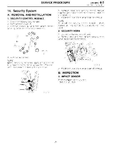
14. Security System                                         5) Remove radio and security control module
                                                            together while disconnecting connector.
1. SECURITY CONTROL MODULE                                  6) Installation is in the reverse order of removal.

1) Disconnect battery ground cable.                         NOTE:
2) Remove front cover (A).                                  To install the security control module, tighten
3) Remove screws (B) and then detach center                 screws securely so that the screws do not come
panel (C) while disconnecting connector.                    loose.
                                                            2. SECURITY HORN
                                                            1) Disconnect battery ground cable.
                                                            2) Remove bolt and then detach security horn
                                                            while disconnecting connector.


                                        B6M1209A

4) Remove two screws.
NOTE:
Before removing the screw, apply a few turns of
butyl tape to the tip of the service tool. This pre-                                                   B6M1340
vents the screw from falling during removal.
                                                            3) Installation is in the reverse order of removal.

                                                            B: INSPECTION
                                                            1. IMPACT SENSOR
                                                            Perform impact sensitivity test.


                                         B6M1339


                                                       25
◦ Jabse Service Manual Search 2024 ◦ Jabse Pravopis ◦ onTap.bg ◦ Other service manual resources online : Fixya ◦ eServiceinfo