Service Manuals, User Guides, Schematic Diagrams or docs for : . Electronic Components Datasheets Active components Transistors RCA cmbt2907
<< Back | HomeMost service manuals and schematics are PDF files, so You will need Adobre Acrobat Reader to view : Acrobat Download Some of the files are DjVu format. Readers and resources available here : DjVu Resources
For the compressed files, most common are zip and rar. Please, extract files with Your favorite compression software ( WinZip, WinRAR ... ) before viewing. If a document has multiple parts, You should download all, before extracting.
Good luck. Repair on Your own risk. Make sure You know what You are doing.
Image preview - the first page of the document
>> Download cmbt2907 documenatation <<
Text preview - extract from the document
CMBT2907
PNP Silicon Planar Epitaxial Transistors
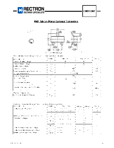
Pin configuration:
1. BASE
2. EMITTER
3. COLLECTOR
3
1
2
Unit: mm
SOT-23 SMD Package
Absolute Maximum Ratings (Ta = 25 oC unless specified otherwise)
DESCRIPTION SYMBOL CMBT2907 CMBT2907A UNITS
Collector Emitter Voltage -VCEO 40 60
Collector Base Voltage -VCBO 60 60 V
Emitter Base Voltage -VEBO 5.0 5.0
Collector Current -IC 600 mA
Power dissipation up to Tamb = 25 oC Ptot 250 mW
Storage Temperature Tstg -55 to +150 o
C
Junction Temperature Tj 150
DC Current Gain
hFE > 30 > 50
-VCE = 10V -IC = 500mA
Turn-off switching time
toff < 100 ns
-ICon = 150 mA; -IBon = IBoff = 15 mA
Transition frequency at f = 100 MHz
fT > 200 MHz
-IC = 50 mA; -VCE = 20 V
Thermal Characteristics
Junction to Ambient in free air Rth(j-a) 500 K/W
Electrical Characteristics (at Ta=25 oC unless otherwise specified)
DESCRIPTION SYMBOL CONDITIONS CMBT2907 CMBT2907A UNITS
Collector Cut Off Current -ICBO IE = 0, -VCB = 50V < 20 < 10 nA
-ICBO IE = 0, -VCB = 50V, Tj=125oC < 20 < 10 uA
-ICEX -VEB = 0.5V, -VCE = 30V < 50
nA
Base Current w/reverse biased emitter junction -IBEX -VEB = 3V, -VCE = 30V < 50
Saturation Voltages -VCE(Sat) < 0.4
-IC = 150mA, -IB = 15mA
-VBE(Sat) < 1.3
-VCE(Sat) < 1.6
-IC = 500mA, -IB = 50mA
-VBE(Sat) < 2.6 V
Collector-base breakdown voltage -V(BR)CBO Open emitter; -IC= 10uA, IE= 0 > 60
Collector-emitter breakdown voltage -V(BR)CEO Open base; -IC= 10mA, IB= 0 > 40 > 60
Emitter-base breakdown voltage -V(BR)EBO Open collector; -IE= 10uA, IC= 0 > 5.0
www.rectron.com 1 of 2
CMBT2907
PNP Silicon Planar Epitaxial Transistors
DC Current Gain hFE -VCE = 10V, -IC = 0.1mA > 35 > 75
-VCE = 10V, -IC = 1mA > 50 > 100
-VCE = 10V, -IC = 10mA > 75 > 100
-VCE = 10V, -IC = 150mA 100 to 300
-VCE = 10V, -IC = 500mA > 30 > 50
Transition Frequency at f = 100 MHz fT -VCE=20V, -IC=50mA > 200 MHZ
Output Capacitance at f = 1 MHz CO -VCB = 10V, IE = Ie = 0 < 8.0 pF
Input Capacitance at f = 1 MHz Ci -VEB = 2V, IC = Ic = 0 < 30 pF
Switching times (between 10% and 90%) -IC = 150mA, -IB = 15mA,
Turn-on time when switched to VCC = 30V
delay time td < 10
rise time tr < 40 ns
turn on time (td + tr) ton < 45
Turn-off time when switched from -IC = 150mA, -IB = 15mA,
to cut-off with + IBM = 15 mA VCC = 6V
storage time ts < 80
fall time tf < 30 ns
turn off time (ts + tf) toff < 100
www.rectron.com 2 of 2
◦ Jabse Service Manual Search 2024 ◦ Jabse Pravopis ◦ onTap.bg ◦ Other service manual resources online : Fixya ◦ eServiceinfo