Service Manuals, User Guides, Schematic Diagrams or docs for : . Electronic Components Datasheets Active components Transistors Wietron mmbt5550-51

<< Back | Home

Most service manuals and schematics are PDF files, so You will need Adobre Acrobat Reader to view : Acrobat Download Some of the files are DjVu format. Readers and resources available here : DjVu Resources
For the compressed files, most common are zip and rar. Please, extract files with Your favorite compression software ( WinZip, WinRAR ... ) before viewing. If a document has multiple parts, You should download all, before extracting.
Good luck. Repair on Your own risk. Make sure You know what You are doing.


Image preview - the first page of the document
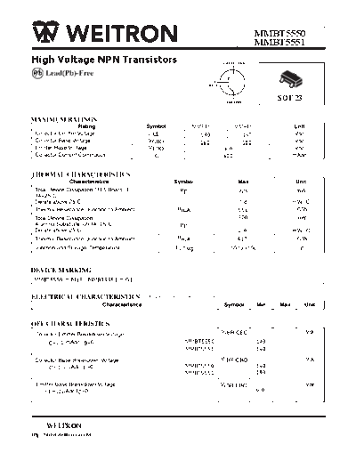
mmbt5550-51


>> Download mmbt5550-51 documenatation <<

Text preview - extract from the document
                                                                                  MMBT5550
                                                                                  MMBT5551
High Voltage NPN Transistors                                         COLLECTOR
                                                                         3
                                                                                                3
                                                                1
                                                             BASE                       1
                                                                                            2
                                                                         2
                                                                      EMITTER
                                                                                        SOT-23


                                                      MMBT5550             MMBT5551
                                   V CEO                140                  160
                                                        160                  180
                                                                     6.0
                                                                     600


                                                                            556
                                                                            300

                                                                            2.4
                                                                            417


 MMBT5550 = M1F ; MMBT5551 = G1

                                  (TA=25 C unless otherwise noted)


                            (3)

          1.0        ,                             MMBT5550                       140
                                                   MMBT5551                       160


          -100       ,                             MMBT5550                       160
                                                   MMBT5551                       180


          10     ,                                                                6.0


      WEITRON
http://www.weitron.com.tw
        MMBT5550
        MMBT5551
ELECTRICAL CHARACTERISTICS (TA=25 C unless otherwise noted) (Countinued)
                            Characteristics                                 Symbol       Min   Max    Unit

OFF CHARACTERISTICS
 Collector Cutoff Current                                                   I CBO
 ( VCB 100 Vdc, I E= 0 )                                    MMBT5550                           100    nAdc
 ( VCB 120 Vdc, I E= 0 )                                    MMBT5551                            50
  ( VCB 100 Vdc, I E= 0 ,TA= 100 C )                        MMBT5550                           100    uAdc
                                                            MMBT5551                            50
  ( VCB 100 Vdc, IE= 0 , TA= 100 C )

  Emitter Cutoff Current
  ( VEB 4.0 Vdc, I C=0 )                                                    I EBO               50    nAdc


ON CHARACTERISTICS
 DC Current Gain                                                  hFE                                  -
  (IC=1.0 mAdc, VCE=5.0 Vdc)                   MMBT5550                             60          -
                                               MMBT5551                             80          -
  (IC=10 mAdc, VCE=5.0 Vdc)                    MMBT5550                             60         250
                                               MMBT5551                             80         250

  (IC=50 mAdc, VCE=5.0 Vdc)                    MMBT5550                             20          -
                                               MMBT5551                             30          -

 Collector-Emitter Saturation Voltage                            VCE(sat)                             Vdc

   (IC=10 mAdc, IB=1.0mAdc)                    Both Types                            -         0.15

   (IC=50 mAdc, IB=5.0mAdc)                    MMBT5550                              -         0.25
                                               MMBT5551                              -         0.20

  Base-Emitter Saturation Voltage                                VBE(sat)                             Vdc

   (IC=10 mAdc, IB=1.0mAdc)                    Both Types                            -         1.0

   (IC=50 mAdc, IB=5.0mAdc)                     MMBT5550                             -         1.2
                                                MMBT5551                             -         1.0

1. FR-5=1.0 x 0.75 x 0.062 in
2. Alumina=0.4 x 0.3 x 0.024 in. 99.5% alumina
3. Pulse Test: Pulse Width = 300 ms, Duty Cycle = 2.0%


     WEITRON
http://www.weitron.com.tw
                                                              MMBT5550
                                                              MMBT5551
                                                   500
                                                   300                                                                                                                                                          VCE = 1.0 V
                                                                             TJ = 125 C
     h FE , DC CURRENT GAIN


                                                   200                                                                                                                                                          VCE = 5.0 V
                                                                           25 C
                                                   100
                                                                           -55 C
                                                          50
                                                          30
                                                          20

                                                          10
                                                    7.0
                                                    5.0
                                                      0.1                        0.2      0.3      0.5    0.7   1.0            2.0   3.0   5.0 7.0   10                                         20   30        50   70    100
                                                                                                                        I C , COLLECTOR CURRENT (mA)

                                                                                                                          FIG.1 DC Current Gain


                                                         1.0
         VCE , COLLECTOR-EMITTER VOLTAGE (VOLTS)


                                                         0.9
                                                         0.8
                                                         0.7
                                                                           IC = 1.0 m A                               10 m A                                     30 m A                              100 m A
                                                          0.6
                                                         0.5
                                                         0.4
                                                         0.3
                                                         0.2
                                                         0.1
                                                              0
                                                              0.005         0.01         0.02         0.05      0.1      0.2          0.5   1.0                             2.0           5.0        10        20         50
                                                                                                                          I B , BASE CURRENT (mA)

                                                                                                                      FIG. 2 Collector Saturation Region


                                                                    1
                                                               10                                                                                          1.0
                                                                                                                                                                   TJ = 25 C
                               I C , COLLECTOR CURRENT (mA)


                                                                           VCE = 30 V
                                                              100
                                                                                                                                       V VOLTAGE (VOLTS)


                                                                                                                                                           0.8

                                                              10-1         TJ = 125 C                                                                              VBE(sat ) @ I C / I B = 10
                                                                                                I C = I CES                                                0.6
                                                                -2
                                                              10                       75 C
                                                                                                                                                           0.4
                                                                -3           REVERSE                FORWARD
                                                              10
                                                                                                                                        ,


                                                                -4                     25 C                                                                0.2
                                                              10
                                                                                                                                                                     VCE(sat )@ IC / I B = 10
                                                                   -5
                                                              10                                                                                            0
                                                                     0.4   0.3     0.2 0.1 0     0.1 0.2 0.3 0.4 0.5             0.6                         0.1     0.2 0.3 0.5 1.0 2.0 3.0 5.0 10 20 30 50                  100
                                                                                   VBE , BASE-EMITTER VOLTAGE (VOLTS)                                                          IC , COLLECTOR CURRENT (mA)

                                                                                       FIG. 3 Collector Cut-Off Region                                                               FIG. 4 "On" Voltages


     WEITRON
http://www.weitron.com.tw
                                                       MMBT5550
                                                       MMBT5551

                                                      2.5
              V , TEMPERA TURE COEFFICIENT (mV/ C)


                                                      2.0                       TJ = - 55 C to +135 C
                                                      1.5
                                                      1.0                                                                                                                                       VBB               VCC
                                                                                                                                                             10.2 V
                                                      0.5                                       q VC for VCE(sat)                                                                                 -8.8V             30 V
                                                                                                                                                                Vin
                                                        0                                                                                                                                          100        3.0 k   RC
                                                     - 0.5                                                                                                                 10 ms          0.25mF    RB
                                                                                                                                                                        INPUT PULSE                                     Vout
                                                     - 1.0                                                                                                                                          5.1 k
                                                                                                        q VB for VBE(sat)
                                                     - 1.5                                                                                                  tr ,t f 10 n s     Vin                 100       1N914
                                                     - 2.0                                                                                                   DUTY CYCLE = 1.0%

                                                     - 2.5
                                                         0.1   0.20.3 0.5 1.0 2.0 3.0 5.0 10 20 30 50                              100
                                                                                                                                                                         Values Shown are for IC@ 10 mA
                                                                       IC , COLLECTOR CURRENT (mA)

                                                                   FIG.5 Temperature Coefficients                                                                       FIG. 6 Switching Time Test Circuit


                                                     100                                                                                                  1000
                                                      70                                                            TJ= 25 C                                                                                      I C / I B = 10
                                                      50                                                                                                  500                                                      TJ = 25 C
     C, CAPACIT ANCE (p F)


                                                     30                                                                                                   300                                            tr @ VCC= 120 V
                                                                                                                                        t , TIM E (n s)


                                                     20                                                                                                   200
                                                                                                                                                                      t r@ VCC = 30 V
                                                     10                                                                                                   100
                                                     7.0                                                        Cibo
                                                     5.0                                                                                                   50            t d@ VEB(off) = 1.0 V

                                                     3.0                                                                    Cobo                           30                VCC = 120 V
                                                     2.0                                                                                                   20

                                                     1.0                                                                                                   10
                                                       0.2 0.3    0.5 0.7 1.0       2.0 3.0                   5.0 7.0 10           20                        0.20.3 0.5       1.0 2.03.0 5.0 10     20 30 50            100 200
                                                                     VR, REVERSE VOLTAGE (VOLTS)                                                                                I C , COLLECTOR CURRENT (mA)

                                                                         FIG. 7 Capacitances                                                                                         FIG. 8 Turn-On Time


                                                                                                       5000
                                                                                                                            t f @ VCC= 120 V                                    IC / I B = 10
                                                                                                       3000
                                                                                                                                                                                 TJ = 25 C
                                                                                                       2000
                                                                                                                                             t f @ VCC = 30 V
                                                                                                       1000
                                                                                      t , TIME (n s)


                                                                                                       500

                                                                                                       300    t s@ VCC = 120 V
                                                                                                       200

                                                                                                       100

                                                                                                        50
                                                                                                          0.2 0.3 0.5   1.0 2.0 3.0 5.0 10 20 30 50                                     100 200
                                                                                                                         I C , COLLECTOR CURRENT (mA)
                                                                                                                               FIG.9 Turn-Off Time


       WEITRON
http://www.weitron.com.tw
       MMBT5550
       MMBT5551

SOT-23 Package Outline Dimensions                                       Unit:mm


                                    A                   Dim Min Max
                                                         A  0.35 0.51
                                                         B  1.19 1.80
                        TOP VIEW            B   C        C  2.10 3.00
                                                         D  0.85 1.05
                                                         E  0.46 1.00
                                D
                                                         G  1.70 2.10
                            G
              E                                          H  2.70 3.10
                            H                            J  0.01 0.13
                                                         K  0.89 1.60
                                            K            L  0.30 0.61
                                                         M 0.076 0.25
                                                L
                                        J           M


     WEITRON
http://www.weitron.com.tw


◦ Jabse Service Manual Search 2024 ◦ Jabse PravopisonTap.bg ◦ Other service manual resources online : FixyaeServiceinfo