Service Manuals, User Guides, Schematic Diagrams or docs for : . Electronic Components Datasheets Active components Transistors Wietron mmbta05-06

<< Back | Home

Most service manuals and schematics are PDF files, so You will need Adobre Acrobat Reader to view : Acrobat Download Some of the files are DjVu format. Readers and resources available here : DjVu Resources
For the compressed files, most common are zip and rar. Please, extract files with Your favorite compression software ( WinZip, WinRAR ... ) before viewing. If a document has multiple parts, You should download all, before extracting.
Good luck. Repair on Your own risk. Make sure You know what You are doing.


Image preview - the first page of the document
mmbta05-06


>> Download mmbta05-06 documenatation <<

Text preview - extract from the document
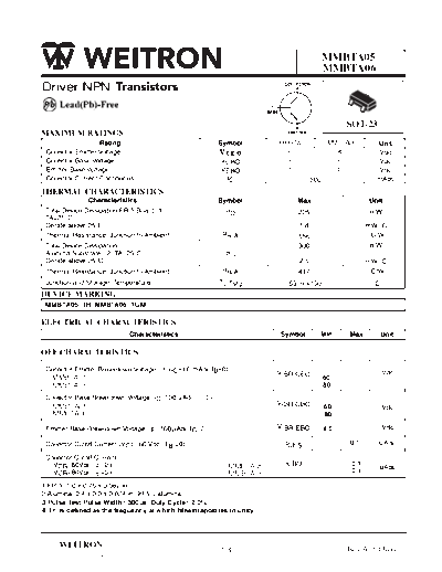
                                                                                 MMBTA05
                                                                                 MMBTA06
Driver NPN                                                                                       3

                                                                                       1
                                                                                             2

                                                                                       SOT-23
                                                                       MMBTA05    MMBTA06
                                                         VCEO            60         80
                                                                         60         80
                                                                         4.0        4.0


 MMBTA05=1H, MMBTA06=1GM


                                     (3)
   MMBTA05                                                                       60
   MMBTA06                                                                       80
                                               0
   MMBTA05                                                                       60
   MMBTA06                                                                       80

                                           0                                     4.0

                                       I B =0)                             S               0.1       u


          6                                                MMBTA05                         0.1
                                                                                           0.1
                                                                                                     u
          8                                                MMBTA06


                            _                  _
3.Pulse Test:Pulse Width < 300us, Duty Cycle < 2.0%
4. f T is defined as the freguency at which hfeextrapolates to unity


      WEITRON                                                                          Rev.A 10-May-10
                                                         1/4
http://www.weitron.com.tw
          MMBTA05
          MMBTA06
     E L E C T R IC A L C HA R A C T E R IS T IC S (T A = 25 C unles s otherwis e noted)
                                                                                        C harac teris tic                                                 S ymbol              Min              Max          Unit


     ON C HA R A C T E R IS T IC S
        DC C urrent G ain
         (I C = 10 mAdc, V C E = 1.0 V dc)                                                                                                                     hF E            100               -               -
         (I C = 100 mAdc, V C E = 1.0 V dc)                                                                                                                                    100               -               -
        C ollector- E mitter S aturation Voltage                                                                                                           V C E (s at)         -
                                                                                                                                                                                                0.25           V dc
           (I C = 100 mAdc, I B = 10 mAdc)
        B as e- E mitter On Voltage                                                                                                                        V B E (on)           -
                                                                                                                                                                                                1.2            V dc
           (I C = 100 mAdc, V C E = 1.0 V dc)

     S MA L L - S IG NA L C HA R A C T E R IS T IC S
        C urrent- G ain - B andwidth P roduct (4)
                                                                                                                                                               fT              100               -           MHz
           (I C = 10 mA, V C E = 2.0 V, f = 100 MHz)


                                      TURN-ON TIME                                                                                                                    TURN-OFF TIME
                                 -1.0 V                                                         VCC                                                            +VBB                  VCC
                                                                                                      +40 V                                                                                +40 V

            5.0 u s                   100                                                             RL                                                              100                  RL
    +10 V                                                                                                        OUTPUT                                                                                  OUTPUT
                          Vin                             RB                                                                                        Vin                   RB
    0                                                                                                              -                                                                                       -
           tr = 3.0 n s
                            5.0 uF
                                                                                                               * CS - 6.0 pF
                                                                                                                                                          5.0 uF                                       * CS - 6.0 pF

                                      100                                                                                                                             100
                                                                                                                                          5.0 us

                                                                                                                                      tr = 3.0 ns


                                                                                        *Total S hunt C apacitance of Tes t J ig and C onnectors
                                                                                         F or P NP Tes t C ircuits , R evers e All Voltage P olarities


                                                                                                F IG 1. S witc hing Time Tes t C irc uits
                                          f T , CURRENT-GAIN - BANDWIDTH PRODUCT(MHz)


                                                                                        300
                                                                                               VCE = 2.0 V
                                                                                        200    TJ = 25 C


                                                                                        100

                                                                                        70

                                                                                        50


                                                                                        30
                                                                                          2.0 3.0          5.0 7.0 10          20    30       50 70 100         200
                                                                                                              IC, COLLECTOR CURRENT (mA)

                                                                                               F IG 2. C urrent-G ain 


◦ Jabse Service Manual Search 2024 ◦ Jabse PravopisonTap.bg ◦ Other service manual resources online : FixyaeServiceinfo