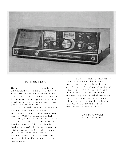
Service Manuals, User Guides, Schematic Diagrams or docs for : . Rare and Ancient Equipment ATLAS MODEL 180 atlas_model_180
<< Back | HomeMost service manuals and schematics are PDF files, so You will need Adobre Acrobat Reader to view : Acrobat Download Some of the files are DjVu format. Readers and resources available here : DjVu Resources
For the compressed files, most common are zip and rar. Please, extract files with Your favorite compression software ( WinZip, WinRAR ... ) before viewing. If a document has multiple parts, You should download all, before extracting.
Good luck. Repair on Your own risk. Make sure You know what You are doing.
Image preview - the first page of the document

>> Download atlas_model_180 documenatation <<
Text preview - extract from the document
                                                                    The high performance and reliability of
               INTRODUCTION                                 the Atlas 180 is enhanced by the finest
                                                            craftsmanship, and a most thorough quality
The Atlas 180 Transceiver is designed for single            control program. Our staff is made up of highly
sideband and CW communications in the 20, 40,               skilled assembly workers, technicians and
80 and 160 meter amateur radio bands. It employs            engineers, many of whom are radio hams.
all solid-state circuitry, with modular construction.       Our service department if and when needed, is
Its conservative 180 Watt power input rating will           dedicated to making every Atlas owner a
provide world-wide communications from fixed,               satisfied customer. Speaking for all the gang at
portable or mobile installations.                           Atlas Radio, we wish you many hours of
         Atlas Radio Inc. is licensed by Southcom           operating pleasure with your atlas 180.
International, Inc. of Escondido Calif.,
manufacturers of military and commercial radio
equipment. With this agreement Atlas Radio is                      73      Herb Johnson W6QKI
able to bring the most advanced, state-of-the-art                          Pres., Atlas Radio, Inc.
circuit designs to the amateur radio market. Les
Earnshaw, founder and director of R & D at
Southcom is considered to be one the foremost
solid state engineers in the world, effectively
proven by the rapid growth of Southcom
International in the military and commercial
markets of the United States as well as many
other countries.


                                                        1
             TABLE OF CONTENTS                                              Operation........................               9,10
                                                                            Antennas, Impedance Matching                      11
                                                                            Antennas, Mobile...............                   12
Technical Specifications.......        2,3                                  PC-100, PC-200 Schematics...                      13
Block Diagram..................          3                                  PC-300, PC-500 Schematics                         14
Special Circuit Features........         4                                  PC-400, PC-600 Schematics                         15
Photos, Top-Bottom-Rear Views          6,7                                  PC-800, PC-900 Schematics                         16
Mobile Installation..............        8                                  Voltage Chart...                  Inside Rear Cover
AC Power Supply Console....              8                                  Chassis Schematic...                          Insert
Linear Amplifier Connections             9


         GENERAL SPECIFICATIONS                                                  RECEIVER SPECIFICATIONS
BAND COVERAGE: 20, 40, 80 and 160 meters.                                CIRCUIT DESIGN: Front end design provides exceptional
                                                                         immunity to overload and cross modulation, matching or out
FREQUENCY RANGES: 1800-2000, 3500-3850, 3700-4050,                       performing the best vacuum tube designs. Signals are converted
7000-7350, 14,000-14,350 kc.                                             directly to the 5520 kc I.F. without preamplification. Converter and
                                                                         product detector are double balanced diode rings. I.C.s are
FREQUENCY CONTROL: highly stable VFO common to both                      employed in the I.F. and A.F. stages.
receive and transmit modes. Tuning dial calibrated in 5 kc
increments with easy interpolation to 1kc. Tuuning rate: 15 kc per       SENSITIVITY: Requires less than 0.3 microvolts for a 10 db
revolution of the tuning knob.                                           signal-plus-noise to noise ratio. (typically 0.2 microvolts)

EXTERNAL FREQUENCY CONTROL: Rear socket provides                         SELECTIVITY: Crystal ladder filter, 8 poles. Bandwidths: 2.7 kc
for plug-in of external VFO or crystal oscillator accessory for          @ 6 db, 4.3 kc @ 60 db, 9.2 kc @ 120 db !! Ultimate rejection
separate control of transmit and receive frequencies or for              more than 120 db !! Shape factor: 1.6
networkand MARS operation.
                                                                         IMAGE REJECTION: More than 60 db.
CIRCUIT DESIGN: All solid state, 4 I.C.s, 18 transistors, 32
diodes. Single conversion, 5520 kc I.F.                                  INTERNAL SPURIOUS: Less than equivalent 1 microvolt signal.

MODES OF OPERATION: SSB: lower sideband on 40, 80, and                   AGC CHARACTERISTICS: Audio output constant within 4 db
160 meters, upper sideband on 20 meters with SB selector switch          with signal variation from 5 microvolts to more than 3 volts.
in NORM. position. Opposite with switch in OPP. Position. CW:
offset frequency in transmit mode.                                       OVERALL GAIN: Requires less than 1 microvolt signal for 0.5
                                                                         watts audio output. (CW carrier, 1000 cycle heterodyne)
MODULAR CONSTRUCTION: Includes plug-in circuit boards
for ease of maintenance.                                                 AUDIO FIDELITY: 300 to 3000 cycles, plus or minus 3 db.

PLUG-IN DESIGN: Transceiver plugs into deluxe mobile bracket,            AUDIO POWER: 2 watts to a 3 ohm speaker with less than 10%
or into the AC power supply console, making transfer or removal a        distortion.
simple operation. All connectors are standard: SO-239 antenna
jack,
◦ Jabse Service Manual Search 2024 ◦ Jabse Pravopis ◦ onTap.bg ◦ Other service manual resources online : Fixya ◦ eServiceinfo