Service Manuals, User Guides, Schematic Diagrams or docs for : . Rare and Ancient Equipment Drake drake_tr-7_operating_sm
<< Back | HomeMost service manuals and schematics are PDF files, so You will need Adobre Acrobat Reader to view : Acrobat Download Some of the files are DjVu format. Readers and resources available here : DjVu Resources
For the compressed files, most common are zip and rar. Please, extract files with Your favorite compression software ( WinZip, WinRAR ... ) before viewing. If a document has multiple parts, You should download all, before extracting.
Good luck. Repair on Your own risk. Make sure You know what You are doing.
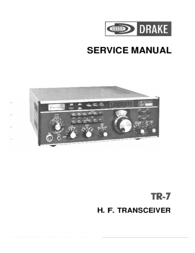
Image preview - the first page of the document

>> Download drake_tr-7_operating_sm documenatation <<
Text preview - extract from the document
SERVICE MANUAL


 H. F. TRANSCEIVER
BD.   *t            DESCRIPTION                          ASSY. #
 1         LOW PaSSFilter Module                      17.18.19.20
 2         T/R Relay                                 Part of LOW Pass
                                                           Filter
           2nd Mixer                                       n7
           VC0
           High Pass Filter Module
           Up-Converter
           Transmit Exciter
           Digital Control
           2nd lF/Audio
           Passband Tuning/Reference
           IFSelectivity
           IFSwitching or NoiseBlanker
           Translator
                              -
           RIT 8 PTO SwitchinclCircuitry
           Power Amplifier Module
           PTO
           AUX-7 Connector
           PowerSupply/Regulator


                    F I ~ 1-3 TR7 Module Locations
                           .
Fig. 2-1 Parent Board Pictorial (Top View)
        (See Page 2-6 for Circuit Side)
Fig. 2-3   Parent Board Pictorial (Bottom View)
Fig. 2-5 Digital Control Board Pictorial
Fig. 2-9 Up-Converter Board Pictorial
    Fig. 2-11 VC0 Board Pictorial
-
                                       TEST PI
                                       /


                                        49


Fig. 2-13 Translator Board Pictorial
Fig. 2-15 2nd Mixer Board Pictorial
-


    Fig. 2-17 IF Switching Board Pictorial
               rork Scle
               naomr m


Fig. 2-19 IF Selectivity Board Pictorial
                                           -

Fig. 2-21 PB TIReference Board Pictorial
Fig. 2-25 2nd IFIAudio Board Pictorial, Version 2
Fig. 2-23 2nd IF/Audio Board Pictorial Version 1
Fig. 2-27 Jumper Board Pictorial
Fig. 2-29 ALC Board Pictorial
     Fig. 2-30 High Pass Filter Parent Board Pictorial
-~


                                                         2-83
Fig. 2-31 High Pass Filter Switch Pictorial (Front & Rear)
Fig. 2-33 Low Pass Filter Board Pictorial (Bands 1-4)
Fig. 2-34 Low Pass Filter Board Pictorial (Bands 5-8)
Fig. 2-35 Low Pass Filter Switch Pictorial (Front & Rear)

                                                            2
Fig. 2-37 Power Supply Board Pictorial
                                            n
                                            R-? U>6
                                                *


Fig. 2-39 Power Amplifier Module Pictorial (wlPredriver Bd. # l )
Fig. 2-40 Predriver Board #2 Pictorial & Schematic

                                                     2-122
2-18. PTO                                                3. Remove the top two screws on each side
                                                             holding the front panel to the side rails, and
The Permeability-Tuned Oscillator (PTO)provides a            loosen the bottom screws.
5.05-5.55 MHz injection signal to the synthesizer        4. Remove the bandswitch knob.
circuitry of the TR-7. The VC0 (Section 2-5) tracks      5. Remove the two screws holding the band-
the frequency of the PTO, thus allowing the                  switch shaft detent to the rear panel and slide
operator to tune through any 500 kHz range via the          .the bandswitch to the rear just enough to clear
front panel tuning control. The PTO has been very            the front panel.
carefully calibrated and temperature compensated         6. The front panel will now hinge down, exposing
a t the factory, and anv attemvt a t remir or revlace-      &L^ D n
                                                                  l
                                                                  p
                                                            rur r L V .
ment of components kill ver; like?; destroy the          7. Refer to figure 2-43 and identify the wrench
calibration andlor compensation. I t is highly recom-       access hole in the rear of the PTO cover. Insert
mended. therefore. that any PTO which requires at-          a long (at least 3") 3/32" ALLEN wrench
tention be returned to the factory for proper repair.       straight through this hole, seating the wrench
                                                            in the ALLEN set screw which serves as the
I t is possible to adjust the knob torque required to
                                                            shaft bearing. The proper wrench is available      .
                                                            from the factory. Be sure to insert the wrench
tune the PTO, should this become necessary. This is         straight through the access hole. to avoid
accomplished as follows:                                    damaging any components inside the PTO.
                                                         8. Carefully adjust the set screw for the desired
                                                            knob torque. Overtightening the adjustment
  1. Remove the two plastic end caps from the sides         screw must be avoided to prevent bearing
     of the front panel. Note that these caps are not       damage.
     identical: there is a right and a left end cap.     9. Reverse the above procedure to reassemble the
  2. Remove the DR7,if installed. (See Section 4-1).        TR-7.


                  Wrench Access
                      Hole


                                    Fig. 2-43 PTO Torque Adjustment
Fig. 4-1 DR7 Removal
Fig. 4-2 DR7 Board Pictorial
Fig. 4-4 AUX7 Board Pictorial
TEST
POINT


        Fig. 4-6 NB-7 Board Pictorial, Version 1
                  TEST POINT


Fig. 4-8 NB-7 Board Pictorial, Version 2
◦ Jabse Service Manual Search 2024 ◦ Jabse Pravopis ◦ onTap.bg ◦ Other service manual resources online : Fixya ◦ eServiceinfo