Service Manuals, User Guides, Schematic Diagrams or docs for : . Rare and Ancient Equipment NEA NewEnglandAnalogAftertouchSensorInstallationInstructions (1)
<< Back | HomeMost service manuals and schematics are PDF files, so You will need Adobre Acrobat Reader to view : Acrobat Download Some of the files are DjVu format. Readers and resources available here : DjVu Resources
For the compressed files, most common are zip and rar. Please, extract files with Your favorite compression software ( WinZip, WinRAR ... ) before viewing. If a document has multiple parts, You should download all, before extracting.
Good luck. Repair on Your own risk. Make sure You know what You are doing.
Image preview - the first page of the document
>> Download NewEnglandAnalogAftertouchSensorInstallationInstructions (1) documenatation <<
Text preview - extract from the document
NEA Aftertouch Sensor Installation Instructions
Thank you for purchasing our aftertouch sensor. We think that you will find it to be superior
to the original in terms of expressiveness and feel. Please follow these installation
instructions to ensure the best performance from this sensor. Have fun!
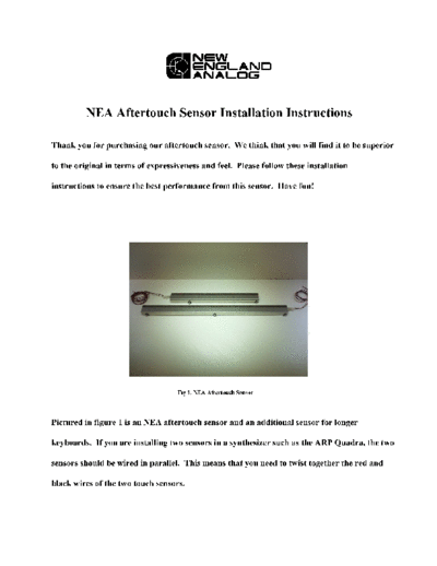
Fig 1. NEA Aftertouch Sensor
Pictured in figure 1 is an NEA aftertouch sensor and an additional sensor for longer
keyboards. If you are installing two sensors in a synthesizer such as the ARP Quadra, the two
sensors should be wired in parallel. This means that you need to twist together the red and
black wires of the two touch sensors.
Before installing the sensor bar, make sure that your key bushings have been replaced
in the last 10 years. If they are dried and cracked, the aftertouch will not be smooth or even
across the keyboard. The metal tongues that the key bushings mount on should all be straight
and aligned to the same height across the keyboard. You do not want some keys to be higher
or lower than neighboring keys.
Fig. 2 Key:in rest position
Fig. 3 Depressed key (Aftertouch not engaged.)
We recommend removing the plastic key tops when doing this installation, as it makes
accessing the metal tabs inside of the keys easier.
It is important to understand a little theory on how this sensor works. Figure 2 shows a
cross sectional diagram of a Pratt Read keyboard mechanism. In this diagram, the touch
sensor bar is mounted beneath the keyboard frame. The bar can just as easily be mounted
above the keyboard frame. To do this, attach the jnuts to the bar, and not the keyboard
frame. We recommend mounting the bars as shown in figure 2. Figure 3 shows the key
mechanism with a key depressed. It is important to note that when a key is depressed at a
normal playing velocity (aftertouch not engaged), the key should be blocked from touching the
felt of the sensor bar by the rubber key bushing. The key sheath should not begin contacting
the felt of the sensor bar until you begin compressing the rubber bushing by pressing down.
Cardboard spacers are used to adjust the height of the bar across the keyboard so that the
geometry is as described above. If a note is too sensitive, adjust the height of the key by
moving the tab that the bushing mounts to in the upward direction. This will cause the bushing
to block the key before it hits the felt. If a note is not sensitive enough, adjust the tab
downward so that the key makes more contact with the sensor when aftertouch is engaged.
The best way to test the uniformity across the keyboard is with an ohmmeter. Connect the
Ohm meter to the red and black wires and depress each key to get a reading. The resistance
should be very high until aftertouch is engaged. Adjust every key using the techniques
described above. When satisfied with the response. Reinstall keyboard in to synthesizer and
wire sensor appropriately.
Fig. 4 Sensors installed in an ARP Quadra keyboard
When installing on synthesizers that did not have a touch sensor previously, it may be
required that you drill additional holes on the underside of the synthesizer to accommodate
any new screws that must be added for stabilization purposes. We usually use a tapping drill
bit that will thread new holes onto the sensor bar from beneath the keyboard.
Good luck with your installation and enjoy your new sensor!
NEA
www.NewEnglandAnalog.com
2077032350
◦ Jabse Service Manual Search 2024 ◦ Jabse Pravopis ◦ onTap.bg ◦ Other service manual resources online : Fixya ◦ eServiceinfo