Service Manuals, User Guides, Schematic Diagrams or docs for : . Various DVD Power Supply Schematics DVD-6054_DVD-6184_LG

<< Back | Home

Most service manuals and schematics are PDF files, so You will need Adobre Acrobat Reader to view : Acrobat Download Some of the files are DjVu format. Readers and resources available here : DjVu Resources
For the compressed files, most common are zip and rar. Please, extract files with Your favorite compression software ( WinZip, WinRAR ... ) before viewing. If a document has multiple parts, You should download all, before extracting.
Good luck. Repair on Your own risk. Make sure You know what You are doing.


Image preview - the first page of the document
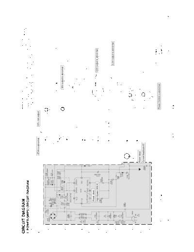
DVD-6054_DVD-6184_LG


>> Download DVD-6054_DVD-6184_LG documenatation <<

Text preview - extract from the document
CIRCUIT DIAGRAM                                                                                                                                IMPORTANT SAFETY NOTICE
                                                                                                                                                WHEN SERVICING THIS CHASSIS, UNDER NO CIR-
                                                                                                                                                                                               CUIT. SPECIAL COMPONENTS ARE SHADED ON THE NOTE :
                                                                                                                                                                                               SCHEMATIC FOR EASY IDENTIFICATION.
                                                                                                                                                                                                THIS CIRCUIT DIAGRAM MAY OCCASIONALLY DIF-
                                                                                                                                                                                                                                            1. Shaded( ) parts are critical for safety. Replace only
                                                                                                                                                                                                                                               with specified part number.
                                                                                                                                               CUMSTANCES SHOULD THE ORIGINAL DESIGN BE
1. POWER(SMPS) CIRCUIT DIAGRAM                                                                                                                 MODIFIED OR ALTERED WITHOUT PERMISSION
                                                                                                                                                                                               FER FROM THE ACTUAL CIRCUIT USED. THIS WAY,
                                                                                                                                                                                               IMPLEMENTATION OF THE LATEST SAFETY AND
                                                                                                                                                                                                                                            2. Voltages are DC-measured with a digital voltmeter
                                                                                                                                                                                                                                               during Play mode.
                                                                                                                                               FROM THE LG ELECTRONICS CORPORATION. ALL        PERFORMANCE IMPROVEMENT CHANGES INTO
                                                                                                                                               COMPONENTS SHOULD BE REPLACED ONLY WITH         THE SET IS NOT DELAYED UNTIL THE NEW SERVICE
                                                                                                                                               TYPES IDENTICAL TO THOSE IN THE ORIGINAL CIR-   LITERATURE IS PRINTED.


                                                                                                       -27VA is abnormal      VF+ not output


                                                                                                                                                                           12V output is abnormal


                                                  Power dead
                                                  High Speed S/W IC                                                                                                                                  3.3V output is abnormal


                                                                                                                                                                                                               3.3V output is abnormal


                                                                                                Power dead
                                                                                                Current feedback IC


                                                                                                                                                                                                      DV7732NS's STM MODEL
                                                                                                                                               Power Control is abnormal                                           '02. 12. 20
    NOTES)   Warning
    NOTES)
    NOTES)
             Parts that are shaded are critical
             With respect to risk of fire or
                                                  NOTES :   Symbol denotes AC ground.

                                                            Symbol denotes DC chassis ground.
                                                                                                                                                                                                                              SI3810
    NOTES)   electricial shock.


                                                                                                                       3-17                    3-18


◦ Jabse Service Manual Search 2024 ◦ Jabse PravopisonTap.bg ◦ Other service manual resources online : FixyaeServiceinfo