Service Manuals, User Guides, Schematic Diagrams or docs for : . Various SM scena API API_MagLink_synchronizer_lit
<< Back | HomeMost service manuals and schematics are PDF files, so You will need Adobre Acrobat Reader to view : Acrobat Download Some of the files are DjVu format. Readers and resources available here : DjVu Resources
For the compressed files, most common are zip and rar. Please, extract files with Your favorite compression software ( WinZip, WinRAR ... ) before viewing. If a document has multiple parts, You should download all, before extracting.
Good luck. Repair on Your own risk. Make sure You know what You are doing.
Image preview - the first page of the document
>> Download API_MagLink_synchronizer_lit documenatation <<
Text preview - extract from the document
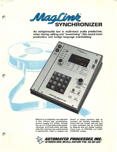
SYNCHRONIZER
An indispensable tool in multi-track audio production;
video mixing, editing and "sweetening"; film sound track
production, and foreign language overdubbing.
MagLink is a completely new approach started at preset positions with an
to fast, efficient tape synchronizing, accuracy not formerly attainable. A
position logging and editing. Through master and any number and any type
the use of a unique timing code system, of slave machines may be controlled
videotape, multi-track audio, and mag by MagLink and will remain synchro
netic film machines may now be locked nized even in REWIND and FAST
in synchronism, offset, or stopped and FORWARD modes.
-T> AUTOMATED PROCESSES, INC.
^>- 80 MARCUS DRIVE, MELVILLE, NEW YORK 11746 516-694-9212
SYlMCHRONi
MagLink acts as a precise "electronic sprocket" coupled SEARCH
to an accurate programmable footage counter which links The search functions can be used to find any position on
and controls any number and any type of tape machines. any or all of the machines in the group.
This is accomplished by means of the MagLink position When the CONTROL ASSIGNMENT switch has selected
code which can be recorded on one track of each tape a slave, entering a 1 to 8 digit position on the keyboard
during the original session or applied later during the mix followed by depressing the SEARCH button will cause the
ing or editing process. A MagLink code converter is avail selected machine to find and assume that position. When
able to accommodate SMPTE coded tapes. A separate the CONTROL ASSIGNMENT switch is in the MASTER
code generator can be used for recording at remote loca
POSITION, the master as well as all slaves will find and
tions. The various modes of operation and their functions assume the selected position. If the AUTOSEARCH button
are discussed below. is pressed at the start of a take, the tape will return to that
starting point each time the SEARCH key is pressed.
SYNCHRONIZATION
PRE-PROGRAMMING
Synchronization can occur between a master tape machine
and up to six slave machines per Model 200 assembly. Using the pre-programming function will allow the master
machine to be synchronized to slaves containing portions
When the AUTO/MANUAL switch is set to AUTO, all
of material located at random throughout the length of
slaves will automatically assume the same stationary posi their tapes.
tion as the master, regardless of where they were, and will
remain stationary until the master tape machine is set in For example, assume the master is a VTR, and one of
motion. the audio slaves contains a number of sound effects which
have to be synchronized with various portions of the master
When this happens, all slaves stay locked to the master,
whether it is in the PLAY or RECORD mode, or in the FAST tape. The requirement may be that, at 10 min., 15 sec, 12
FORWARD or REWIND mode. frames on the master a sound effect located at 1 min., 5
sec, 10 frames on the slave should be in sync with the
In the latter two modes, synchronization will be main master until 10 min., 20 sec, 20 frames of the latter (cue 1).
tained regardless of the speed of the machines, and in Also, from 15 min., 10 sec, 10 frames, to 18 min., 0 sec,
the case of most machines available today, regardless of 0 frames, the master is to be synced to material located on
whether or not the tape is lifted away from the heads. Bear the slave at 20 min., 10 sec, 10 frames (cue 2); and from 20
in mind that no modifications to the tape machines are re
min., 20 sec, 0 frames, to 20 min., 40 sec, 18 frames on the
quired. However, connections to the remote motion con master, material located at 8 min., 8 sec, 8 frames on the
trols are necessary. This is a simple process and data is slave (cue 3).
provided. These connections are required for the master
and the slaves. Additionally, connections are made to the The synchronizer will be programmed as follows (before
drive motor of each slave. or while the machines are in motion):
Set the CONTROL ASSIGNMENT switch to MASTER,
the START/FINISH switch to START, and enter 10 15 12,
OFFSET and depress the ENTER key; then set the CONTROL
The term OFFSET denotes the constant difference in posi ASSIGNMENT to the first slave and enter 1 5 10, and
tion maintained between two machines in motion. For depress the ENTER key, return the CONTROL ASSIGN
example, one slave may always be .5 second behind the MENT switch to MASTER, set the START/FINISH switch to
master. Offset can be created in either of two ways: FINISH, and enter 10 20 20, depress the ENTER key. Finally,
enter the cue number ("1") and depress the ENTER key.
A. The CONTROL ASSIGNMENT switch is used to select
the appropriate machine. Then, using the keyboard, any The same procedure is repeated to enter the remaining
desired offset (up to 31 hours) may be entered and the data, and can be written in a shorter form thus:
OFFSET key depressed. As soon as the OFFSET key has MASTER START/10 15 12/ENTER
been depressed, the slave will assume the offset. The SLAVE START/1 5 10/ENTER
actual offset is indicated by the lower half of the POSI MASTER FINISH/10 20 20/ENTER, 1/ENTER
TION READOUT in units determined by the READOUT
MASTER START/15 10 10/ENTER
CONVERSION SELECTOR. SLAVE START/20 10 10/ENTER
If a negative offset is required, i.e., if a machine is to MASTER FINISH/18 0 0/ENTER, 2/ENTER
fall behind the others, the number entered on the key etc.
board is preceded by the minus sign (--). When the master tape machine is set in motion, the
B. Pushing the ADVANCE or RETARD button will cause the slave will go to position 15 10 and wait. Then, when the
selected machine to increase or decrease it's speed master reaches 10 15 12, the slave will go into synchro
at the rate of 2 frames (.07 second) per second with nization until 10 20 20, at which time it will unlock, and
respect to the others, thus causing an offset. When the go to position 20 10 10 to wait for the master to reach
button is released, this offset will be retained, even if 15 10 10, whereupon it will be in synch as shown above.
the machines are stopped, started, and run in fast for The slave will always assume a waiting position which
ward or rewind. is located sufficiently ahead of the entered position, to be
Regardless of which way offset is achieved, zero off completely in sync with the master when it reaches that
set can be restored automatically by simply pressing the position.
OFFSET key. Offset mode operation is verified by the To change any individual cue, enter the new data along
OFFSET INDICATOR. with the cue number of the cue to be changed. The old data
will then be erased from the memory and the new data in
serted in the correct sequence. In order to erase the entire
S Y N C H R O N I Z E R F R O N T PA N E
memory prior to pre-programming a new show, set the
CONTROL ASSIGNMENT SELECTOR to CANCEL and
press the ENTER key. An accessory memory unit makes
it possible to permanently store and retrieve pre-program
med data.
TIMING CODE CLOCK
The code clock can be set to "zero", or to any point in time
through the use of the keyboard and the RESET key. There
is an internal switch in the rack equipment for use with
color sync (NTSC).
A "Jam Sync" feature allows the clock to synchronize
with a pre-existing time code and continue consecutive
time. This is useful when doing insert recording ("drop
ins") or add-ons. It eliminates the necessity of re-recording
the entire time code in order to achieve a consecutive
count. To synchronize the clock with a pre-recorded time
code on the tape simply press the RESET key, then put the
code track in Record to cause the time code to be re
corded beyond that point. In synchronization, a consecu
tive count is not required, but may be a convenience for
editing point computations. On the other hand, a "time of
day" clock may be preferred when "take" identification is
of prime importance.
SELECTABLE CONVERSION DISPLAY
The MagLink control panel will display the machine posi
tions in units that are commonly used in different applica
tions, as indicated by the 5-position READOUT CONVER
SION SELECTOR. Additional readout displays may be re-
moted if required.
In the first three positions of the CONVERSION SEL
ECTOR, the first six digits display hours (0-23), minutes
(0-59) and seconds (0-59). The last two digits display
frames (0-29), frames (0-24), or tenths of seconds.
In the last two positions the first digits display feet
(0-9999), and the last two, 16mm frames or 35mm frames
(0-39 and 0-15 respectively).
Since all position codes are derived from the same basic
code format, the CONVERSION SELECTOR can be moved
to any position at any time during recording or playback.
The DISPLAY HOLD and FRAME READ switches are for
ease in reading the display while the tape machines are in
motion. Pressing the DISPLAY HOLD button "freezes" the
display instantly, permitting the accurate readout of a cue
location. The FRAME READ switch unblanks the last two
digits on the right of the display. The count or identity of
these rapidly changing digits is constantly known by the In the PRE-PROGRAM mode, the true positions of mas
system even though the display normally will not show ter and selected slave are displayed. True positions are also
them. With this switch they can be recalled at will, typically displayed in the MANUAL mode in which the machines operate
when the display is frozen or when the machines are at rest. as conventional independent tape drives.
In the AUTO mode, the slave portion of the readout (con In addition to the synchronizer controls, the only other
cerning the particular slave selected by the CONTROL AS controls required to operate the tape machines are those
SIGNMENT SELECTOR) reads the offset of that slave from normally needed to run the master machine, and an optional
the master. It will show 00 if there is no offset, and master RECORD button for each slave. These RECORD buttons, are
and slave are in sync. provided since it is possible to RECORD as well as PLAY BACK
When achieving a particular offset, or returning to "dead" from a tape in sync.
sync, the readout will show progress toward or away from Through the correct interface module, the MagLink output
the 00 point. Whenever a keyboard entry is made, that entry can be made compatible with any type of machine. The unit will
will be displayed on the readout, temporarily displacing the control synchronous motors as well as servo or other voltage
pre-existing display until the action is called for; and then controlled motors. Contact closures are provided for audio
the progress toward that action will occupy the display. mute, etc. during search or slewing.
I POSITION READOUT 9 SEARCH KEY
Upper half displays the position of the master Entering a position on the keyboard, followed by
tape; lower half displays the position, or offset, depressing the SEARCH key, will command a
of any slave as determined by the CONTROL selected tape machine to search for and then
ASSIGNMENT SELECTOR (4). wait at this position. See AUTOSEARCH (5).
2 FRAME READ CONTROL 10 RESET KEY
This "press to activate--twist to lock" switch Used to reset the code generator when starting
a time code recording. Set the desired starting
permits reading the FRAMES or .1 SEC portion
of the POSITION READOUT which is normally point with the keyboard and enter by depressing
blanked for ease of operation. the RESET key.
11 OFFSET KEY
3 DISPLAY HOLD CONTROL Entering a number, followed by depressing the
Press to "freeze" the display while tape is in OFFSET key, will immediately create an offset
motion; twist button to hold display while between one selected machine and all other ma
logging. chines in the system.
4 CONTROL ASSIGNMENT SELECTOR 12 --(MINUS) KEY
Determines which machine will be affected by Provides the selected machine with a negative
EM the operation of controls (6) thru (14). It will also offset or "retard".
determine which slave is monitored on the PO 13 CLEAR KEY
SITION READOUT. The CANCEL position per
Used to clear incorrect data entry.
mits the entire pre-program memory to be
erased when the ENTER key (8) is pressed. 14 KEYBOARD
Used to enter offsets and tape positions in con
5 AUTOSEARCH BUTTON junction with switches (8) thru (13). Any num
Used for repeated automatic return to start of ber entered on the keyboard will be shown on
take, etc. Used in conjunction with SEARCH the POSITION READOUT, and will temporarily
key (8). Present position may be entered by replace the machine position otherwise dis
pressing the AUTOSEARCH button. Later, played.
pressing the SEARCH key will cause the ma 15 READOUT CONVERSION SELECTOR
chine to return to that point.
Converts the position display to the format
6 START/FINISH SWITCH selected by the switch.
Used in conjunction with the ENTER key (8) and 16 PROGRAM INDICATOR
the CONTROL ASSIGNMENT SELECTOR (4) to
pre-program a sequence of operations. In the Lights when in the PRE-PROGRAM mode.
START position, the switch permits entry of the 17 OFFSET INDICATOR
position of the MASTER at which a slave is to
start in sync. An entry made with the switch in Lights when the selected slave is commanded
the FINISH position determines the point at to be displaced with respect to the MASTER.
which the slave will "unlock" out of sync and 18 SYNC INDICATOR
either stop or search for the next start point.
Lights when machines are locked in synchron
7 ADVANCE AND RETARD BUTTONS ism, with or without offset.
Depressing the ADVANCE or RETARD button 19 RECORD BUTTONS
will speed up or slow down the selected ma Control the RECORD functions of each of the
chine, thus creating an offset which will be dis slave machines.
played on the POSITION READOUT, and which
will be maintained when the button is released. 20 AUTO/MANUAL SWITCH
In the AUTO mode, MagLink controls machines
8 ENTER KEY connected to it. In the MANUAL mode, the posi
Used in conjunction with START/STOP switch tions of the machines are monitored, but they
(6). are not controlled by MagLink.
Model 250 Motor Drive Amplifier for Slave
BASIC SYSTEM AND ACCESSORIES (required for synchronous motors)
Model 200 Basic MagLink System for 1 Master, 1 Slave. Model 210 Separate Self-powered Code Generator
Includes Code Generator and Model 211 Code Generator with Precision Crystal
1 No. 241 Memory Card. Clock
Part No. 205 Interface Equipment for each additional Model 220 SMPTE to MagLink Code Converter
slave-- Model 230 Additional Readout Display in Cabinet
Consists of: Relay Interface Card* Part No. 241 Additional Memory Card for One Hundred
Capstan Control Card* Cues
Logic Card
Set of two Filter Cards Part No. 244 Additional Memory Card for Four Hundred
Cues
'Specify manufacturer and model number of master and each
slave to be connected to MagLink to assure correct Model 260 Memory Unit for Permanent
interface. Pre-Program Storage
SYNCHRONIZER
T Y P I C A L A P P L I C AT I O N S
1 SYNCHRONIZING AUDIO SYNCHRONIZING VIDEO
TAPE RECORDERS TAPE RECORDERS
AUDIO INPUTS VIDEO
{ 11 CAPSTAN
AND MOTION
III VIDEO
SWITCHER
ATR CONTROLS ATR
(MASTER) (SLAVE) SWITCH
CONTROL
III
AUDIO OUTPUTS Mxs'Ask
Ml
AUDIO OUTPUTS
VR
T
(MASTER)
CONTROL VTR
(SLAVE)
CODE CODE CODE CODE
_l L_
1
CONTROL VTR
-dflSfgflglS: (SLAVE)
MagLink will keep two or more ATR's in sync. For ex
ample, two 16 track ATR's can be connected to func
tion as a single 30 channel ATR by means of the edit
1 CODE
_J |
code recorded on one track of each tape.
AUTOSEARCH simplifies repeated shuttling back to MagLink will operate two or more VTR's in sync, in
the beginning of a take or cue point. accordance with predetermined cues entered in the
pre-programming mode. This permits spliceless editing
OFFSET sync provides continuously variable or fixed and previewing with inexpensive slant track tape. Edit
tape delay effects. ing of the original quad tapes may then be automatical
ly accomplished, using the previously programmed edit
code format. The pre-programming function may also
be used for audio tape editing.
SYNCHRONIZING AUDIO AND
VIDEO TAPE RECORDERS
SYNCHRONIZING SPROCKETED
AUDIO INPUTS
MAGNETIC TAPE RECORDERS
HELICAL TRACK
CAPSTAN
AND MOTION
CONTROLS
i i WITH CONVENTIONAL
ATR
VTR
(MASTER) (SLAVE) AUDIO RECORDERS
AUDIO INPUTS
SPROCKET
JL
_
AUDIO OUTPUTS ATR
ATR
(SLAVE)
(MASTER)
MagLink will keep one or more ATR's synchronized AUDIO OUTPUTS
with a VTR while recording for audio "sweetening." The
edit code is recorded on both the ATR and VTR while
a helical video dub is made from the quadruplex
master.
After completion of the audio mix the "sweetened" MagLink will keep one or more audio tape recorders
audio is recorded on the audio track of the Quadruplex in perfect synchronism with a sprocketed multi-track
VTR master tape from the ATR. Perfect synchronization magnetic film master by means of the edit code pre
is maintained throughout the entire sweetening process viously recorded on one track of each tape. After the
(including offsets where necessary for lip sync.) by recording of additional tracks on the ATR, the final mix
means of the edit code. is recorded on the sprocketed master. In the manner
described in (2), one or more multi-track magnetic film
machines may be synchronized with a VTR master.
r
OUAD VTR CONTROL ATR
(MASTER) (SLAVE)
CODE CODE
Mz@◦ Jabse Service Manual Search 2024 ◦ Jabse Pravopis ◦ onTap.bg ◦ Other service manual resources online : Fixya ◦ eServiceinfo