Service Manuals, User Guides, Schematic Diagrams or docs for : MAKITA 51018-WW-1
<< Back | HomeMost service manuals and schematics are PDF files, so You will need Adobre Acrobat Reader to view : Acrobat Download Some of the files are DjVu format. Readers and resources available here : DjVu Resources
For the compressed files, most common are zip and rar. Please, extract files with Your favorite compression software ( WinZip, WinRAR ... ) before viewing. If a document has multiple parts, You should download all, before extracting.
Good luck. Repair on Your own risk. Make sure You know what You are doing.
Image preview - the first page of the document
>> Download 51018-WW-1 documenatation <<
Text preview - extract from the document
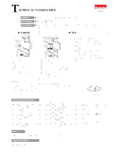
T           ECHNICAL INFORMATION                                                                                                        51018

               Subject                   Changes on change plate, spindle and some relevant parts

               For Models                HP1500, HP1510, HP1501

               Description               As described below, the parts in the subject have been changed for improvement in
                                         endurance.


              Current                                                                         New
                                                                               1'                1. Against seizure of spindle and cam;
                                  1
                                                                                                   A plane bearing is added to the cam complete.
                                                                               2'
                                                                                                 Diameter of the cam holder's hole which
                                   2
                                                                               6                 receives the cam is enlarged. Inner and outer
                                                                                                 diameters of the cam is enlarged.
                                  3                                            3'                2. Against abrasion of change plate in drilling
                                                                                                 mode; Pin 4 is added to disperse the load on the
                                   4                                           4'                change plate (surface contact of pin 4 while
                                                                                                 point contact of steel ball 4.8). The change
                                                                               7                 plate is improved in hardness. The grease
                                  5
                                                                                                 stocked around the steel ball makes lubrication
                                                                               5'                life longer.
  1 cam holder                                 1' cam holder (reformed)
  2 cam                                        2' cam (reformed)
  3 spindle                                    3' spindle (reformed)
  4 steel ball 4.8                             4' steel ball 3.5 (changed to smaller one)
  5 change plate                               5' change plate (reformed and hardened)
  * Cam holder complete consists               6 plane bearing (added)
    of 1 and 2                                 7 pin 4 (added)
                                               * Cam holder complete consists of 1', 2' and 6.


Important)
When replacing these parts be sure to fill up the hole of the spindle with grease for longer                       Grease here depression
librication life before setting the steel ball 3.5 and the pin 4 in place. Also provide enough grease
on the surface of the change plate where it contacts with the pin 4 (the shaded area of the change
plate as illustrated on the right).
                                                                                                                              change plate
                                                                                                                      (view from the spindle side)


 Interchangeability(I/C)

   Item No.         Current part                        Q'ty    I/C           New part                           Q'ty              Note
      23       Change Plate                                            Change Plate
                                                         1      No                                                1
               344112-2                                                344419-6
               Spindle                                                 Spindle
      17                                                 1      No                                                1
               322674-0                                                322900-7                                          No interchangeable
       22      Steel Ball 4.8                                          Steel Ball 3.5                                    as a set
                                                         1      No                                                1
               216002-8                                                216001-0
       37                                                              Pin 4
                                                                       256251-5                                   1
               Cam Holder Complete                             <=      Cam Holder Complete
       25                                                1                                                       1
               152473-4                                                152529-3

 Note
    Interchangeability mark; <= means that the new part can be substituted for the current.

  Implementation
   From Dec., 1995
◦ Jabse Service Manual Search 2026 ◦ Jabse Pravopis ◦ onTap.bg ◦ Other service manual resources online : Fixya ◦ eServiceinfo