Service Manuals, User Guides, Schematic Diagrams or docs for : MAKITA 6951-TE

<< Back | Home

Most service manuals and schematics are PDF files, so You will need Adobre Acrobat Reader to view : Acrobat Download Some of the files are DjVu format. Readers and resources available here : DjVu Resources
For the compressed files, most common are zip and rar. Please, extract files with Your favorite compression software ( WinZip, WinRAR ... ) before viewing. If a document has multiple parts, You should download all, before extracting.
Good luck. Repair on Your own risk. Make sure You know what You are doing.


Image preview - the first page of the document
6951-TE


>> Download 6951-TE documenatation <<

Text preview - extract from the document
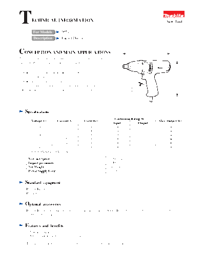
T        ECHNICAL INFORMATION

                                 6951
                                                                                                                    New Tool

           For Models
           Description           Impact Driver


CONCEPTION AND MAIN APPLICATIONS                                                              239 mm (9-3/8")

This new impact driver is developed as an improved model of the
current #6950 and its main features are as follows:-


                                                                                                                           180 mm (7-1/8")
1. A new reverse switch, located near the trigger switch, ensures
   one-hand operation.
2. A new trigger switch with variable speed control has a wider
   variable speed control length of trigger for easir operation.
                                                                                    60 mm
3. Ergonomics design of handle for comfortable operation.                          (2-3/8")


    Specifications
                                                                          Continuous Rating(W)
         Voltage(V)           Current(A)           Cycle(Hz)                                                    Max. Output(W)
                                                                         Input            Output
            100              3.2                        50/60             300              120                       280
            120             *2.8                        50/60             300              120                       280
            200              1.6                        50/60             300              120                       280
            220              1.5                        50/60             300              120                       280
            230              1.4                        50/60             300              120                       280
            240              1.3                        50/60             300              120                       280
     *U.S.A.,CANADA :120V, 3.2A

       No Load Speed                                                0~2200rpm/min
       Impact per minute                                            0~3000
       Net Weight                                                   1.3kg (2.9lbs)
       Power Supply Cord                                            2.5m (8.2ft)


    Standard      equipment
     Phillips Bit 2-65...1
     Plastic Carrying Case...1


    Optional      accessories
     Phillips Bit 2-65, 3-65 Stopper (for depth adjustment of screw) Socket Bit 7-55, 8-55, 10-55, 10-70, 12-86, 13-55, 14-55,
     17-55, 17-65, Bit piece


    Features      and benefits
     1. Double insulated
     2. See the attached sheets for more information.

     The Standard equipment for the tools shown may differ from country to country.
Newly designed variable speed control
                                                                             Slide-Type Reversing Switch
switch with a wider speed control length
of trigger for easier operation.                                            Assures one-hand operation.
(to see the chart and the graph below)

                                                                             Ergonomics design of handle
                                                                            for comfortable operation


                                            Stopper (optional)
                                           for easier depth adjustment of screw
(4) Attaching Spindle complete and Hammer assembly to Housing :
                                                                                                Gear
    Joint Flat washer with Ball bearing as the right figure, and place
    them into Housing.


(5) Attaching of Ball bearing 607LB :
    As only one side is sealed in Bearing of Armature rear part, direct
    an open side toward the rear end and attach it.
                                                                                            Flat washer
                                                                                                              Ball bearing
                                                                                                     Fig. 3

                                                                                                              Spindle
(6) Disassembly of Hammer                                                          Swelling part
                                                                                                                   Cum groove top
    Press down Hammer with Arbor, put the insert entrance of Steel ball
    in Hammer together with the cum groove top of Spindle as the right
    Figure.4, and pull out Steel ball. Then, direct Hammer downward
    and remove Spindle complete, being careful that Steel ball inside                                                   Hammer
    Hammer may not fall out.                                            Steel ball
                                                                          insert entrance


                                                                                                                         Gear


                                                                                                     Fig. 4
(7) Notes in Field exchange
    Since Lead wires go out of the both ends in Field as Fig. 1, install as Fig. 2 so that Yellow terminal plate may be located in
    Fan side of Armature.


                                                                                   Yellow terminal plate


                                                           Black                White
                                                                      Yellow


                                                                       Fig. 1


                                                                    Yellow terminal plate
                            Brush holder
                                    Brush holder connecting wire (purple)


                                                            Field


                          Holder arm


                                              Housing L


                                                                                  Switch
                                                             Fig. 2
                                                                                       Field
Circuit   diagram
Area where two Noise suppressors are used                       Commutator side                      Fan side


                                                                                                             Orange
                                                                                                       White
                                                                                                                                      Yellow
                                                                                                   Purple
                                                                        Choke coil             Black
                                       White

                                                                                               M1 M3 4          2        3   1
                                                            Insulated
                                                            connector                                        White
                                                                          Earth terminal
                                                                                                                                      Switch
                         Insulated                                        ( for Field
                         connector                                         steel plate)
                                                                                                    C1 C2 M2 11 21
                                                                          Clear
                                                                                       Black

                                                                                                                    P1           P2
                                               Noise               Noise
                                               suppressor          suppressor                                Power supply cord


                                                                                       Field
Other area
There are areas where neither Choke coil nor                    Commutator side                     Fan side
Noise suppressor is used.


                                                                                                            Orange
                                                                                                            White
                                                                                                       Purple                         Yellow
                                                                          Choke coil
                                                                                           Black

                                                                                               M1 M3 4          2        3   1

                                                                                                             White
                                                                                                                                      Switch

                                                                                                    C1 C2 M2 11 21


                                                                                                                P1               P2
                                                                   Noise
                                                                   suppressor                                Power supply cord


◦ Jabse Service Manual Search 2024 ◦ Jabse PravopisonTap.bg ◦ Other service manual resources online : FixyaeServiceinfo