Service Manuals, User Guides, Schematic Diagrams or docs for : MAKITA 6953-TE

<< Back | Home

Most service manuals and schematics are PDF files, so You will need Adobre Acrobat Reader to view : Acrobat Download Some of the files are DjVu format. Readers and resources available here : DjVu Resources
For the compressed files, most common are zip and rar. Please, extract files with Your favorite compression software ( WinZip, WinRAR ... ) before viewing. If a document has multiple parts, You should download all, before extracting.
Good luck. Repair on Your own risk. Make sure You know what You are doing.


Image preview - the first page of the document
6953-TE


>> Download 6953-TE documenatation <<

Text preview - extract from the document
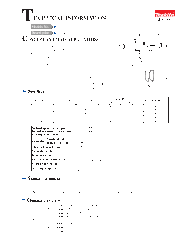
T     ECHNICAL INFORMATION
    Models No.                 6953
                                                                                                                NEW TOOL
                                                                                                                  P1/6

    Description                Impact Wrench
                                                                                                     L
CONCEPT AND MAIN APPLICATIONS
   The above model is the impact wrench with
   max. fastening torque, 150N.m.
   This model's brief features and benefits are
   * palm fitting soft grip
   * Removable belt clip can be attached on both left                                                                     H
     and right side without any tool.
                                                                                                W

                                                                    Dimensions : mm ( " )
                                                               Length ( L ) 233 (9-1/8)
                                                               Height ( H ) 180 (7-1/8)
                                                               Width ( W )   67 (2-5/8)
  Specification
                                                                             Continuous Rating (W)
       Voltage (V)            Current (A)             Cycle (Hz)                                         Max. Output(W)
                                                                            Input           Output
           110                     2.7                    50 / 60            280              120             240
           120                     2.5                    50 / 60            280              120             240
           220                     1.3                    50 / 60            280              120             240
           230                     1.3                    50 /60             280              120             240
           240                     1.2                    50 / 60            280              120             240

    No load speed (min-1=rpm)                          0 - 3,000
    Impact per minute (min-1=bpm)                      0 - 3,000
    Driving shank : mm ( " )                           12.7 (1/2)
                Standard bolt                        M10 - M16
    Capacities
                High Tensile bolt                     M8 - M12
    Max. fastening torque                           150 N.m (110 ft.lb)
    Variable switch                                       Yes
    Reverse switch                                        Yes
    Protection from electric shock                  by Double insulation
    Cord length : m ( ft )                             2.5 (8.2)
     Net weight: kg (lbs)                              1.4 (3.1)


 Standard equipment
   * Plastic carrying case .......................... 1 pc.


   < Note > The standard equipment for the tool shown may differ from country to country.

 Optional       accessories
   * Socket 17-38          * Socket 23-38          * Universal joint
   * Socket 17-52          * Socket 23-52          * Extension bar
   * Socket 19-38          * Socket 24-45          * Bit adapter
   * Socket 19-52          * Socket 24-52          * Oval socket assembly
   * Socket 21-38          * Socket 26-50
   * Socket 21-52          * Socket 26-78
   * Socket 22-38          * Socket 21-78
   * Socket 22-52          * Socket 19-78
Features   and benefits                                                                               P2/6


                Max. fastening torque : 150 N.m


                                                Compact size : 233mm


  12.7mm square drive


         High rigid aluminum
         internal gear case                                            Push button type reverse switch
               and
         hammer case

   Variable speed switch : Easy to control the speed                        Palm fitting soft grip


    Enough distance of more than 30mm
    to clip easily on your belt for transportation


                                                                           Tough cord guard
                                                                           Excellent in flexibility
                                                                           to protect the cable
                                                                           from disconnection

             Toolles detachable belt clip.
             Can be attached on both left and
             right sides
Repair                                                                                                           P3/6
< 1 > Disassembling housing set
      1) Take off 4 pcs. of hex socket head bolts M4x30. And then, remove hammer case and internal gear case
         from housing. See Fig. 1.
      2) Take off 7 pcs. of tapping screws 4 x 18. So. housing can be removed. See Fig. 1.


                                     Hex socket
                                     head bolt M4x30 : 4 pcs.


         Hammer case

              Internal gear case

                                                                                               Tapping screw
                                                                                               4 x 18 : 7 pcs.
                    Carbon brush
         Brush holder cap


                                                          Fig. 1
< 2 > Assembling anvil
      Assemble rubber ring 18 and flat washer 18 into hammer case. And then, assemble anvil on which grease has been
      applied in advance. See Fig. 2.
       Make sure that bracket has been assembled between hammer case and internal gear case.


                                                    hammer case
                                                          Bracket
                                                                Rubber ring 18
                                                                    Flat washer 18


                                                                             Anvil
                                                                                       Internal gear case


                    Apply 0.1 g of MAKITA grease N No.1 to the cylinderic portion of anvil
                    marked with black triangle, to protect parts and machine from unusual abrasion.
                                                          Fig. 2
Repair                                                                                                           P4/6
< 3 > Disassembling hammer
       (1) Press down hammer with 1R045: Large gear extractor
          by turning the handle.

      (2)Adjust the opening for steel ball inserting to the cam groove top of spindle.
                                                                                                    Spindle
      (3)Take off 2 pcs. of steel balls 5.6 from spindle.               Cam groove top
      < Note > 25 steel balls 3.5 are installed in hammer.              of spindle
               Check the quantity when assembling.


                                                       Steel ball 5.6 x 2

        1R045 Large gear extractor
                                                                                                               Hammer
                                                              Opening for steel
                                                              ball inserting


                                                      Steel ball 3.5 x 25


                                                                                     Fig. 3

       (4) Apply grease to the position No. 1, 2, 3 and 4 as listed below, when assembling.

                                      (3) to Steel ball 5.6 x 2

                                                                                              (1) to Spindle
                                      (2) to Steel ball 3.5 x 25

                MAKITA        Molybdenum                                                            Hammer
                grease N No.1 di-sulphide lubricant
       (1)          0.5g            0.2g
       (2)          0.5g
       (3)                              0.6g
       (4)          1.0g                0.2g
                                                                                                (4) to Spur gear 22
                                                                   Fig. 4                Ball bearing 6901LLB
Repair                                                                                                   P5/6
< 4 > Assembling housing R and L
     When assembling housing R to housing L, make sure that 2 pcs. of rubber pins 4 have been attached
     to the illustrated portion of housing R. See Fig. 5.


                                                         Rubber pins 4


                                                           Housing R


                             Housing R
                                                         Fig. 5

< 5 > Hammer case has to be fastened diagonally as illustrated in in Fig.6.


                                                                              Hammer case


                                                          Fig.6
Circuit   diagram
                                                         Color index of lead wires
                                                                                                                     P6/6

                                                    Black
          Holder arm                                White
          complete                                  Orange
                                                    Purple
                                                    Transparent

                                                                                              Field


                             1    Switch                  M1
                                              1      4
                            2          M2
   Power supply
                                              3      2
   cord                     C1 C2                         M3


                          Noise
                          suppressor

            The products may come with noise suppressor of 2 lead wire type, or without noise suppressor
            for some countries.

                                            Field has to be so assembled, that its
Wiring     diagram                          poke-in terminals face to the holder
                                            arm complete side.
       Holder arm
       complete                                                               Boss

                                                                                     Pass the lead wire (orange) between field
                                                                                     and boss as per the illustration.

                                            Field

                                                                                       Lead wire (white)
                                                                                       connecting main switch
                                                                                       with reverse switch.

                                 Rib
                                                                                               Hold the lead wire (white)
 Pass the lead wires inside of this rib.                  Switch                               with lead holder on the switch.

  Holding the lead wire
  (transparent) with lead holder,
  pass between switch and
  housing's wall as per
  the illustration.
                  Lead holder                Noise
                                             suppressor                      The products may come with noise suppressor
                                                                             of 2 lead wire type, or without noise suppressor
                                                                             for some countries.


◦ Jabse Service Manual Search 2024 ◦ Jabse PravopisonTap.bg ◦ Other service manual resources online : FixyaeServiceinfo