Service Manuals, User Guides, Schematic Diagrams or docs for : MAKITA 6980FD-TE

<< Back | Home

Most service manuals and schematics are PDF files, so You will need Adobre Acrobat Reader to view : Acrobat Download Some of the files are DjVu format. Readers and resources available here : DjVu Resources
For the compressed files, most common are zip and rar. Please, extract files with Your favorite compression software ( WinZip, WinRAR ... ) before viewing. If a document has multiple parts, You should download all, before extracting.
Good luck. Repair on Your own risk. Make sure You know what You are doing.


Image preview - the first page of the document
6980FD-TE


>> Download 6980FD-TE documenatation <<

Text preview - extract from the document
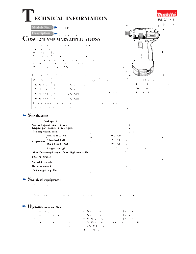
T     ECHNICAL INFORMATION
    Models No.                  6980FD
                                                                                                 L
                                                                                                             PRODUCT
                                                                                                               P1/ 9

    Description                 Cordless impact driver
CONCEPT AND MAIN APPLICATIONS
  The above product has been launched in the market,
  having the following features.
  * With built-in LED job light                                                                                 H
  * Newly designed hammer case from which the projections for
    screw holes has been removed for increased maneuverability.
  * Phosphorescent (glow-in-the dark) bumper
  * Max. fastening torque: 125 N.m
                                                                                   W
   The variations of this model are as listed below.
    Model No.                          Battery           Q'ty         Charger                     Dimensions : mm ( " )
    6980FDWA              Battery 1222 Ni-Cd 2.0 Ah       1                                  Length ( L )   163 (6-3/8)
    6980FDWAE             Battery 1222 Ni-Cd 2.0 Ah       2                                  Width ( W )      94 (3-11/16)
                                                                      DC1414                 Height ( H )   235 (9-1/4)
    6980FDWDE             Battery 1234 Ni-MH 2.6 Ah       2
    6980FDWFE        Battery 1235 Ni-MH 3.0 Ah       2
    These 4 models come with battery cover and plastic carrying case together
    with the above charger and battery.


 Specification
              Voltage (V)                                                         12.0
    No load speed (min-1=rpm)                                                   0 - 2,600
    Impact per minute (min-1=bpm)                                               0 - 3,200
    Driving shank: mm ( " )                                                   6.35 (1/4) Hex
                Machine screw                                           M4 - M8 (5/32" - 5/16")
    Capacities Standard bolt                                            M5 - M12 (3/16" - 15/32")
                High Tensile bolt                                       M5 - M10 (3/16" - 3/8")
                Coarse thread                                         22 - 125mm (7/8" - 5") in length
    Max. fastening torque : N.m (Kgf.cm)[in.lbs]                           125 (1,270) [1,100]
    Electric brakes                                                                Yes
    Variable switch                                                                Yes
    Reverse switch                                                                 Yes
    Net weight: kg (lbs)                                                         1.6 (3.5)


 Standard equipment
   * Battery cover ......................... 2 pcs.
   * Plastic carrying case ............. 1 pc.

   < Note > The standard equipment for the tool shown may differ from country to country.


 Optional       accessories
   * Various socket bits                * Battery 1220 Ni-Cd 1.3Ah      * Charger DC1414
   * Various drill chuck set            * Battery 1222 Ni-Cd 2.0Ah      * Charger DC1439
   * Bit piece                          * Battery 1234 Ni-MH 2.6Ah      * Charger DC1804
   * Stopper for impact driver          * Battery 1235 Ni-MH 3.0Ah      * Automotive charger DC1422
                                        * Battery 1235A Ni-MH 3.0Ah
                                                   w/Power display
                                                                                                              P2/9

Features             and benefits

                                                 Compact Design with an Overall
                                                 Length of 163mm (6-3/8")

 Hammer Case of New Design
 Elimination of screw hole protrusions                                                    Powerful and Compact
 reduces possibility of scratches on                                                      D28 Type DC Motor
 materials in operation, increasing
                                                                                      *Rare earth magnet provides
 maneuverability to a great extent.
                                                                                       strong power.
                                                                                      *Motor life is extended by efficient
                                Eliminated                                             cooling, replaceable armature, and
                                                                                       externally accessible carbon brush.


                                                                                         Rubberized Soft Grip
                    LED Job light
                                                                                    Is ergonomically contoured to fit
                 For illuminated operation                                          your palm perfectly for much more
                                                                                    comfortable and controlled operation.
   Phosphorescent
   (glow-in-the dark) bumper                                                           Hand strap can be attached.
 Enables you to easily find this tool
 in dark locations.
                                                                                       14.4 V Cluster Type Battery
   Easy-to-Operate Large Trigger Switch
   for Variable Speed Control


Comparison               of products
                             Model No.                     Makita                             A
      Specifications                          6980FD       6916FD        6919D                A
               Voltage : V                      12            12           12                 12
 Battery


               Current capacity : Ah            2.6           2.6          3.0                1.7
               Battery cell                   Ni-MH        Ni-MH        Ni-MH               Ni-Cd
  Charging time : min.                       approx. 60   approx. 60   approx. 27         approx. 45
 Max.                                           125           100          110               115
 fastening torque : N.m [ in.lbs]             [1,110]        [887]        [960]            [1,000]

 No load speed (min-1=rpm)                   0 - 2,600     0 - 2,300    0 - 2,600          0 - 2,400
 Impact per minute (min-1=bpm)               0 - 3,200     0 - 3,000   0 - 3,200           0 - 3,000
 Material of hammer case                     Aluminum     Magnesium    Magnesium         Magnesium
 LED job light                                  Yes          Yes          Yes                 No
 Externally accessible brush                    Yes          Yes          Yes                 No
 Soft grip                                      Yes          Yes          Yes                Yes
                                                163          165          163                167
                 Length : mm [ " ]
                                              [6-3/8]       [6-1/2]     [6-3/8]            [6-9/16]
  Dimensions


                                                 94           94           94                 82
                 Width : mm [ " ]             [3-11/16]    [3-11/16]    [3-11/16]           [3-1/4]

                                                235           231          222               235
                 Height : mm [ " ]
                                              [9-1/4]       [9-1/8]      [8-3/4]            [9-1/4]
 Net weight : Kg [lbs]                           1.5           1.5         1.6                1.7
                                               [ 3.3 ]       [ 3.3 ]     [ 3.5 ]            [ 3.7 ]
                                                                                                                      P3/ 9

 Comparison       of products
   Numbers in the charts below are relative values when the results for Model A of the competitor A
   has been indexed at 100.
   < Note > The working speed and amount may differ, depending on the condition of wooden materials.

                                                 Comparison in fastening work
                                                                                         Fastening amount
                                       Driving single speed                              with one fully charged battery
   Testing condition
    * Material: Spruce   * Fastener : Coarse thread 41mm
                                       Slow        Fast                                      Few         Many

MAKITA 6980FD (2.6Ah)                      110                     0.6 sec.                        190     720 pcs.
MAKITA 6916FD (2.6Ah)                      100                                               185

   A        A    (1.7Ah)                   100                                    100

MAKITA 6317D (2.6Ah)                        90                                               160
(high speed mode)

                           0   20     40        60    80     100   120        0   50     100       150 200 250       300
   Testing condition
    * Material: Spruce   * Fastener : Coarse thread 90mm
                                       Slow        Fast                                      Few         Many

MAKITA 6980FD (2.6Ah)                      105                     4.8 sec.                    180              85 pcs.

MAKITA 6916FD (2.6Ah)                      100                                                 170

   A        A    (1.7Ah)                   100                                    100

                           0   20     40        60    80     100   120        0   50     100       150 200 250       300

   Testing condition
    * Material: Spruce   * Fastener : Lag bolt 1/4"
                                      Slow            Fast                                   Few         Many

MAKITA 6980FD (2.6Ah)                      110                     5.5 sec.                    175              65 pcs.

MAKITA 6916FD (2.6Ah)                      100                                                 175

   A        A    (1.7Ah)                   100                                         100
MAKITA 6317D (2.6Ah)
                                            95                                                 210
(low speed mode)

                           0   20     40        60    80     100   120        0   50     100       150 200 250       300


                                                     Comparison in drilling

   Testing condition                 Drilling single speed                               Drilling amount
    * Material: Spruce   * Bit : Auger bit 1"                                            with one fully charged battery

                                      Slow            Fast                                   Few         Many

MAKITA 6980FD (2.6Ah)                      105                     6.5 sec.                        190          60 pcs.

MAKITA 6916FD (2.6Ah)                      100                                                   180

   A        A    (1.7Ah)                   100                                    100

MAKITA 6317D (2.6Ah)                       105                                                  250
(low speed mode)
                           0   20     40        60    80     100   120        0   50     100       150 200 250       300
                                                                                                                   P4/ 9
Repair
1) Disassembling
1) -1. Disassembling Sleeve Section (Fig. 1)
      (1) Remove ring spring from the groove on anvil.
      (2) Now flat washer, compression spring 13, sleeve and 2 pcs of steel ball 3.5 can be removed from anvil.
      (3) Anvil can be removed from hammer case.
      Fig. 1

                                Compression spring 13
                  Ring spring          Sleeve Groove             Steel ball 3.5 x 2 pcs.


                                                Anvil
                     Flat washer                                   Apply Makita grease N.No.2 to the
                                                                   cylindrical portion of anvil before mounting.


1) -2. Removing Hammer Case Complete
     (1) Pull LED circuit section out of housing by removing PT3 x 10 tapping screw. ( Fig. 2)
     (2) Remove stopper by removing PT3 x 16 tapping screw. (Fig. 2)
      Fig. 2


                                                                                                      Stopper


                                                                                                    Tapping screw
                                          LED circuit                                               PT3 x 16
                                          section
        Tapping screw
        PT3 x 10

     (3) Remove bumper from hammer case. (Fig.3)                 Fig. 3

     (4) Fit socket 30-78 (Part No.134847-1) over the hex
        portion of hammer case.
        And then remove hammer case from housing by
        turning the socket clockwise as illustrated in Fig. 4.
                                                                                                       Bumper


      Fig. 4
            Hammer case


                                             Socket 30-78
                                             (134847-1)
                          Hex portion
                          of hammer case
                                                                                                            P5/9

Repair
1) -3. Disassembling Housing
   (1) After removing brush holder caps and carbon brushes, remove hammer section, ring 41 and internal gear 51
        from housing. (Fig. 5)
   (2) Remove internal gear 51 by unscrewing 4 pcs. of pan head screw M4x12. (Fig. 6)
   (3) Remove eight PT3x16 tapping screws. Now housing R can be separated from housing L. (Fig. 7).

  Fig. 5                                                    Fig. 6


             Internal gear 51   Ring 41                        Internal gear case       Pan head
                                          Hammer section                                screw M4x12
     Carbon brush
                                                                                            < Note >
                                                                                            The pan head screws
                                                                                            M4x12 are adhesive ones.
                                                                                            It is recommended
                                                                                            to employ impact driver
                                                                                            for unscrewing them.
    Brush holder
    cap


  Fig. 7


                                                                        Tapping screw
                                                                        PT3x16


                                                                     Housing R


                Housing L
                                                                                                                  P6/9

Repair
1) -4. Disassembling Hammer and Spindle Section
      (1) Press down hammer with Large gear extractor (1R045) by turning the handle. (Fig. 8)
      (2) Adjust the opening for steel ball insertion to the top of cam groove on spindle. (Fig. 8)
      (3) Remove 2 pcs of steel ball 5.6 from spindle. (Fig. 8)
      (4) Hold the hammer section as illustrated in Fig. 9, and then loose the handle of large gear extractor.
         Caution: Do not hold gear extractor as illustrated in Fig. 8 when loosening the handle of gear extractor.
                  Failure to follow this instruction could cause steel balls 3.5 to get out of hammer.
      (5) Now hammer section can be disassembled as illustrated in Fig. 10.
      (6) After removal of flat washer 24, steel balls 3.5 can be removed from hammer. (Fig. 11)

      Fig. 8                                                                    Fig. 9

                               Spindle
                                                      Steel ball 5.6
          Top of cam groove
          on spindle


          Opening for steel                                   Hammer
          ball insertion


      Fig. 10                                                                        Fig. 11

           Spindle section

                                                               Flat washer 12
                                              Pin 5                                                       Hammer


         Cup                                                                                              Steel ball 3.5
         washer 14                                                                                        (24 pcs.)

        Compression
        spring 25                                                 Spur gear 22
                                             Spindle
                                                                                                          Flat washer 24

          Hammer
                                                                                                                P7/9

Repair
2) Assembling
2) -1. Assembling Sleeve Section
    Do the reverse of disassembling procedure.
2) -2. Assembling Hammer and Spindle Sections
    (1) Before assembling the parts, apply Makita grease N. No.2 to the following parts.
        * Top of the spindle where anvil contacts: approx. 0.5 g
        * 2 pcs of steel ball 5.6: approx. 0.5 g
        * 24 pcs of steel ball 3.5 which are mounted to hammer: approx. 0.5 g
        * 2 pcs of spur gear 22: approx. 2.0 g
   (2) And then do the reverse of disassembling procedure. (Fig. 11, 10, 9 and 8)
       Note: Make sure that all of 24 steel balls (size = 3.5) are installed on hammer. (Fig. 11)
2) -3. Assembling Housing
     When assembling the housing, be sure to follow the instructions below.
       1. Before mounting the internal parts, make sure that rubber pin 4 is installed on
          each of housing R and L. ( Fig. 12)
       2. When mounting FET and FET spacer to yoke unit, tighten a ST3x8 tapping screw
          to the recommended torque of 1.1 - 1.5N.m (11 - 15kgf.cm). (Fig. 13)
       3. When fastening housing R to housing L, tighten each of eight PT3x16 tapping screws
          to the recommended torque of 1.1 - 1.3N.m (11 - 13kgf.cm). (Fig. 14)
       4. When mounting LED circuit section, tighten a tapping screw PT3 x 10
          to the recommended torque of 0.54 - 0.66N.m (5.3 - 6.5 kgf.cm).
          (See Fig. 2 in page 4.)
   Fig. 12


               Housing L                                                                      Housing R
                                        Switch


                                                     Rubber pin 4
                                      Make sure that rubber pin 4 is installed on
                                      each of housing R and L.

   Fig. 13                                             Fig. 14

                                      Yoke unit                                                     Tapping screw
                                                                                                    PT3x16 (8 pcs)

                                   FET spacer

                                     FET
                                     (Field effect
                                     transistor)

                                                                                                       Housing R
         Tapping screw
         ST3x8
                                                         Housing L
                                                                                                                P8/9

Repair
    2) -4. Assembling Hammer Case to Housing
    (1) When mounting internal gear case to housing, be sure to follow the instructions below. (Fig. 15)
        * Always use brand-new M4x12 pan head screw.
        * Tighten each of four M4x12 pan head screws to the
          recommended torque of 0.88 - 1.8 N.m (9.0 - 18 kgf.cm).

    (2) Fit socket 30-78 (Part No.134847-1) over the hex portion of hammer case, and then tighten
        the socket to the recommended torque of 25 - 30 N.m (260 - 310 kgf.cm). (Fig.16)
        Caution:
        Do not fail to install anvil on hammer case before fastening hammer case to housing.

    Fig. 15                                           Fig. 16
                                                                                         Hammer case
      Internal gear case Pan head screw M4x12


                                                                                                 Anvil


                                                                                      Hex portion            Socket 30-78
                                                                                      of hammer case         (134847-1)


    (4) Install stopper on housing.
        Caution:
        Because stopper is not reversible when installed on housing, be sure to place it as illustrated in Fig. 17.
    Fig. 17


                                                                Correct
                                                                                          Stopper


                                                                Wrong
                                                                                                       P9/9
Circuit   diagram
  Endbell                                                     Color index of lead wires' sheath
                                                               Black
                                                               Red


                                                 FET
                                                 (Field Effect Transistor)


                                         M2
                                                                              LED circuit
                                  M1

                               Switch


Wiring    diagram
                                         Before installation of internal parts

                                                                                 Put the slack portion of LED
                                                                                 lead wires here.

                                                                                                  LED circuit
                                                                                                  section


  After installation of internal parts                                                  Boss

                                                                                   Put the following lead wires
 Endbell complete                                                                  deep in the lead holder.
                                                                                    * Lead wire (black) of LED
                                                                                    * Lead wire (red) of LED


                    Motor

                                                  FET


                                                    LED circuit
                      Switch
   Rib                                              section

                                           Route endbell lead wire (black)
                                           between FET and the rib.


◦ Jabse Service Manual Search 2024 ◦ Jabse PravopisonTap.bg ◦ Other service manual resources online : FixyaeServiceinfo