Service Manuals, User Guides, Schematic Diagrams or docs for : MAKITA 71250-WW-1

<< Back | Home

Most service manuals and schematics are PDF files, so You will need Adobre Acrobat Reader to view : Acrobat Download Some of the files are DjVu format. Readers and resources available here : DjVu Resources
For the compressed files, most common are zip and rar. Please, extract files with Your favorite compression software ( WinZip, WinRAR ... ) before viewing. If a document has multiple parts, You should download all, before extracting.
Good luck. Repair on Your own risk. Make sure You know what You are doing.


Image preview - the first page of the document
71250-WW-1


>> Download 71250-WW-1 documenatation <<

Text preview - extract from the document
TECHNICAL INFORMATION
Subject                Modification of Housing Set and Guide Plate,
                                                                                                           71250
                                                                                                         ( Page 1 of 2 )

                       Addition of Stopper Plate, Sub Plate, Torsion Spring 9 and M4x8 Pan Head Screw
For Models             BHR200
Country                All countries
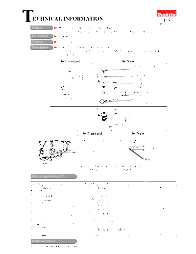
Description            Housing set and Guide plate have been modified.
                       Stopper plate, Sub plate, Torsion spring 9 and M4x8 pan head screw have been added.
                       See illustration below for the detail.

                             Current                                         New
                                                                                   Pan head screw M4x8
                                                                                   (911110-7)
                                                                                   Sub plate
                                                                                   (345456-3)
                                                                                   Stopper plate
                                                                                   (345458-9)
                                                                                   Guide plate
                          Guide plate                                              (345457-1)
                          (344900-7)
                                                                                   Torsion spring 9
                                                                                     (231678-0)


                                                                               The new parts are assembled
                                                                               as the left.


                                                 Current                             New


                                                                                               3mm up to 4mm


                                                                                               Deleted
          (Housing (L) complete)
                                        Left side of Housing set   Left side of Housing set
                                               (152864-9)                 (154525-7)

Interchangeability(I/C)
Item No.      Current part                 Q'ty I/C         New part                    Q'ty             Note
         Housing Set                                 Housing Set
050, 088                                     1    No                                     1
         183393-1                                    183891-5
         Guide Plate                                 Guide Plate
  075                                        1    No                                     1
         344900-7                                    345457-1
                                                     Stopper Plate
    092                                                                                  1         Interchangeable
                                                     345458-9
                                                                                                        as a set
                                                     Sub Plate
    093                                                                                  1
                                                     345456-3
                                                     Torsion Spring 9
    094                                                                                  1
                                                     231678-0
                                                     Pan Head Screw M4x8
    095                                                                                  1
                                                     911110-7

 Implementation
From serial No. 90836E (August, 2004)
                                                                                                                  71250
                                                                                                              ( Page 2 of 2 )

Steps to replace the relevant parts
Remove Guide plate, Change plate and Compression spring 4 from machine in advance.

1) After putting Stopper plate on the new Guide plate, hold them with Sub plate by screwing M4x8 Pan head screw
   as Fig. 1.
          Fig. 1
                                                    Pan head screw M4x8 (911110-7)
                                                    Sub plate (345456-3)

                                                    Stopper plate (345458-9)

                                                    Guide plate (345457-1)


2) Insert Torsion spring 9 into the hole of stopper plate as Fig. 2, and then hook it on Guide plate as Fig. 3.

          Fig. 2                                    Fig. 3


            Torsion spring 9
              (231678-0)
3) Put Change plate between Stopper plate and Guide plate.


                                               (Change plate)


4) See Fig. 4.
   Pre-set Change lever to "Hammer mode", and then secure
   them with two 4x12 Tapping screws.
   Hook compression spring 4 on Guide plate and Change plate.
   Shift Change lever to "Hammer drill mode" so that Change plate does not come out of place.


                       (Tapping screw 4x12)


(Change lever)                    (Compression spring 4)

              (Tapping screw 4x12)


◦ Jabse Service Manual Search 2024 ◦ Jabse PravopisonTap.bg ◦ Other service manual resources online : FixyaeServiceinfo