Service Manuals, User Guides, Schematic Diagrams or docs for : MAKITA 9558NB-TE

<< Back | Home

Most service manuals and schematics are PDF files, so You will need Adobre Acrobat Reader to view : Acrobat Download Some of the files are DjVu format. Readers and resources available here : DjVu Resources
For the compressed files, most common are zip and rar. Please, extract files with Your favorite compression software ( WinZip, WinRAR ... ) before viewing. If a document has multiple parts, You should download all, before extracting.
Good luck. Repair on Your own risk. Make sure You know what You are doing.


Image preview - the first page of the document
9558NB-TE


>> Download 9558NB-TE documenatation <<

Text preview - extract from the document
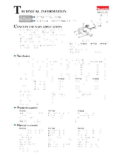
T     ECHNICAL INFORMATION
   Models No.                  9556NB, 9557NB, 9558NB
                                                                                                                                       PRODUCT
                                                                                                                                         P 1 / 13

   Description                 Angle Grinders 100/115/125mm (4/ 4-1/2/ 5")                                                   L


CONCEPT AND MAIN APPLICATIONS
   The 9556NB series models have been developed as upgraded
   sister tools of the current 9526NB series models.                                                    H
   In masonry cutting, perform better than the current series models                               W
   thanks to the following benefits:
   *Powerful 840W motor with excellent heat resistance
   *Labyrinth structures around bearings and dust-proof motor                                                Dimensions: mm (")
                                                                                      Model No.            9556NB       9557NB      9558NB
   AC/DC switch is used for the tools for USA and other                               Length (L)                      271 (10-5/8)
   North American countries.
                                                                                      Width (W)           118 (4-5/8) 129 (5-1/8) 139 (5-1/2)
                                                                                      Height (H)         97 (3-13/16)       106 (4-3/16)

 Specification
                                                                                 Continuous Rating (W)
      Voltage (V)             Current (A)             Cycle (Hz)                                                            Max. Output(W)
                                                                                Input           Output
           110                    8.0                   50 / 60                  840              500                              1000
           120                    7.5                   50 / 60                  840              500                              1000
           220                    4.0                   50 / 60                  840              500                              1000
           230                    3.8                   50 / 60                  840              500                              1000
           240                    3.7                   50 / 60                  840              500                              1000

    Model No.                                                      9556NB                     9557NB                           9558NB
                      Depressed center wheel                       100 (4)                   115 (4-1/2)                       125 (5)
                      Wire cup brush                                75 (3)                                      90 (3-1/2)
    Capacity: mm (")
                      Abrasive disc                                100 (4)                   115 (4-1/2)                         125 (5)
                      Diamond wheel                                100 (4)                   115 (4-1/2)                         125 (5)
    No load speed: min.-1 = rpm                                                                11,000*
    Spindle thread                                         M10x1.5/ M10x1.25                                DIN/ 5/8"-UNC
    Cord length: m (ft)                                                                        2.5 (8.2)
    Net weight: kg (lbs)                                                                       1.6 (3.5)
    *North America =10,000
 Standard equipment
   9556NB                                          9557NB                                              9558NB
   Depressed center wheel 100-36 .... 1            Depressed center wheel 115-36 .... 1                Depressed center wheel 125-36 .... 1
   Lock nut wrench 20 ...................... 1     Lock nut wrench 28 ...................... 1         Lock nut wrench 35 ...................... 1
   Grip 36 complete .......................... 1   Grip 36 complete .......................... 1       Grip 36 complete .......................... 1
   Note: The standard equipment for the tool shown above may differ by country.

 Optional        accessories
   9556NB                                          9557NB                                              9558NB
   Depressed center wheel 100-24                   Depressed center wheel 115-24                       Depressed center wheel 125-24
   Depressed center wheel 100-36                   Depressed center wheel 115-36                       Depressed center wheel 125-36
   Rubber pad 76                                   Rubber pad 100                                      Rubber pad 115
   Sanding lock nut 10-30                          Sanding lock nut 14-48                              Sanding lock nut 14-48
   Assorted 100mm abrasive discs                   Assorted 115mm abrasive discs                       Assorted 125mm abrasive discs
   Wire cup brush 75                               Super flange 47                                     Super flange 47
   Wire bevel brush 85                             Dust extracting wheel guards                        Dust extracting wheel guards
   Base assembly                                   Dust extracting wheel cover                         Dust extracting wheel cover
   Wheel cover
   Dust extraction attachment
                                                                                                                    P 2 / 13
Features              and benefits

  Powerful 840W Motor with                                                        *      Labyrinth Construction
                                                                                                                               *
                                               High Dust-Proof Motor
  Excellent Heat Resistance                                                              Protects All Ball Bearings
                                             Armature coated with protective
  Ensures steady and efficient               zigzag varnish, and Field coated            from Dust and Debris.
  masonry cutting.                           with powder varnish protects motor
  (840W = continuous rating input)           from dust and wire breakage,             Motor with High             *
                                             ensuring durability enough for           Heat-Resistance Performance
  Rotatable Gear Housing *                   masonry cutting.
                                                                                      See the graph below.
 Can be positioned at every
 90 degrees to suit most cutting
 and grinding operations.

 Shaft Lock for     *
 Easy Wheel Changes

   Dust-proof Ball Bearing           *
 On spindle and the commutator
 end of armature; a dust-proof                                               Small Circumference Barrel Grip                   *
 washer is also installed on spindle.                                        for Easy Handling
 O Rings for Protection from *                                             Use of Type 55 motor enables the circumference
 Grease-Leakage                                                            to be smaller than competitions. And use of the
                                                                           same brush as used for the Makita 9560 series
 Placed in the following portions;                                         models allows flat design without protrusions of
 1) Joint between Gear housing and                                         brush cap.
    Bearing box
 2) Shaft lock pin installation hole                                     Gear Section with Increased Reparability *
 Switch Lever Conveniently Located *                                    Use of a woodruff key to assemble gear onto spindle
                                                                        allows for easier repairing of gear section.
      for One Hand Operation
 The same advantage as the Makita 9560
 series models.                                                              (*Same advantages as 9553NB series models)


 Comparison of Heat Resistance Performance
 Test conditions: Continuously cut 600mm wide concrete plate at a depth of 10mm with an identical diamond wheel
                  attached to all the models, and measured the temperature rise in the field.
 Test result: The graph below proves the superiority of Makita 9557NB in heat-resistance performance.


                120


                100


                 80                                                                                 Competitor B Mod. B
  Temperature
   (degree C)


                 60                                                                                 Makita 9527NB

                                                                                                    Competitor A Mod. A3
                 40                                                                                   (Mod. A4)

                                                                                                    Competitor C Mod. C
                 20

                                                                                                    Makita 9557NB
                  0
                      0                  5                         10                          15
                                                  Time (min.)
                                                                                                               P 3 / 13
Comparison             of products
 [1] 9556NB and 9558NB
                                                      100mm (4")                       125mm (5")
                        Model No.
                                                        Makita                           Makita
 Specifications                             9556NB            9526NB           9558NB           9528NB
                                              100                  100           125                125
                       Diameter
 Wheel size:                                  (4)                  (4)           (5)                (5)
 mm ( " )                                      16                16             22.23            22.23
                       Hole diameter
                                              (5/8)             (5/8)           (7/8)            (7/8)
 Continuous rating input: W                   840                  750           840                750
 Rated amperage for USA: A                    7.5                   ---          7.5                6.4
 Max. output: W                              1,000                 850          1,000               850
                            -1
 No load speed: min              = rpm       11,000            11,000           11,000           11,000
 (for USA)                                  (10,000)          (10,000)         (10,000)         (10,000)
 AC/DC switch for USA                         Yes                  No            Yes                No
                                             53 x 63          55 x 64          53 x 63          55 x 64
 Size of grip portion: mm (")
                                         (2-1/16 x 2-1/2) (2-3/16 x 2-1/2) (2-1/16 x 2-1/2) (2-3/16 x 2-1/2)
 Circumference of                              195               195             195              195
 grip portion: mm (")                        (7-5/8)           (7-5/8)         (7-5/8)          (7-5/8)
 Double insulation                            Yes                  Yes           Yes                Yes
 Cord length: m (ft)                        2.5 (8.2)         2.5 (8.2)        2.5 (8.2)        2.5 (8.2)
                                              271               256              271              256
               Length: mm (")
                                            (10-5/8)          (10-1/8)         (10-5/8)         (10-1/8)
  Dimensions


                                               118               118             139              139
               Width: mm (")
                                             (4-5/8)           (4-5/8)         (5-1/2)          (5-1/2)
                                               97                111             106              111
               Height: mm (")
                                            (3-13/16)          (4-3/8)         (4-3/16)         (4-3/8)
 Net weight: Kg (lbs)                       1.6 (3.5)         1.4 (3.1)        1.6 (3.5)        1.4 (3.1)
           Side Grip                          Yes                  Yes           Yes                Yes
 Standard
 equipment Lock nut wrench                    Yes                  Yes           Yes                Yes
           Wheel                              Yes                  Yes           Yes                Yes
                                                                                                                        P 4 / 13
Comparison             of products
 [2] 9557NB
                                                                             115mm (4-1/2")
                         Model No.                      Makita                 Competitor A    Competitor B      Competitor C
                                                                                A3 (USA)
                                            9557NB               9527NB                              B                 C
 Specifications                                                                 A4 (Euro)
                                               115                 115             115               115              115
                       Diameter
 Wheel size:                                 (4-1/2)             (4-1/2)         (4-1/2)           (4-1/2)          (4-1/2)
 mm (")                                       22.23               22.23           22.23            22.23             22.23
                       Hole diameter
                                              (7/8)               (7/8)           (7/8)            (7/8)             (7/8)
 Continuous rating input: W                    840                 750             750              750               800
 Rated amperage for USA: A                     7.5                 6.4              7                 7                ---
                                                                               a) 880W (A3)
 Max. output: W                               1,000                630                            b) 780               ---
                                                                               b) 835W (A4)
                            -1
 No load speed: min              = rpm       11,000               11,000         11,000            11,000           11,000
 (for USA)                                  (10,000)             (10,000)
 AC/DC switch for U.S.A.                       Yes                 No              Yes               No                ---
                                             53 x 63          55 x 64           59 x 62           56 x 68            62 x 62
 Size of grip portion: mm (")
                                         (2-1/16 x 2-1/2) (2-3/16 x 2-1/2) (2-5/16 x 2-7/16) (2-3/16 x 2-11/16) (2-7/16 x 2-7/16)
 Circumference of                              195                 195             202              203               199
 grip portion: mm (")                        (7-5/8)             (7-5/8)           (8)              (8)             (7-1/8)
 Double insulation                             Yes                 Yes             Yes              Yes               Yes
 Cord length: m (ft)                        2.5 (8.2)            2.5 (8.2)       2.5 (8.2)        2.5 (8.2)         2.5 (8.2)
                                              271                  256             284              281               250
               Length: mm (")
                                            (10-5/8)             (10-1/8)        (11-1/8)         (11-1/8)          (9-7/8)
  Dimensions


                                               129                 129             132              138               131
               Width: mm (")
                                             (5-1/8)             (5-1/8)         (5-3/16)         (5-7/16)          (5-1/8)
                                              106                  111             102               112              118
               Height: mm (")
                                            (4-3/16)             (4-3/8)           (4)             (4-3/8)          (4-5/8)
 Net weight: Kg (lbs)                       1.6 (3.5)            1.4 (3.1)      1.55 (3.4)        1.8 (3.9)         1.6 (3.5)
                     Side Grip                 Yes                 Yes             Yes              Yes               Yes
 Standard
 equipment Lock nut wrench                     Yes                 Yes             Yes              Yes               Yes
           Wheel                               Yes                 Yes             No                No               Yes
 a) Actual wattage of low voltage machine measured by us
 b) Actual wattage of high voltage machine measured by us
                                                                                                                 P 5 / 13
Comparison      of products
Performance Comparison of Cutting/ Grinding - 1] Europe
Models Tested for Comparison: Makita 9557NB, 9527NB, Competitor A's Mod. A4, Competitor B's Mod. B,
                                     Competitor C's Mod. C
1) EFFICIENCY OF CONCRETE CUTTING
Test conditions:
Cut concrete continuously at depths of 10mm and 20mm with an identical diamond wheel attached to all the models,
and measured the time required to cut a certain length.
Test results: See the graphs below.
       Note: 1. The test results depend to a great extent on the hardness of materials, etc.
              2. The numbers in the bar graphs are relative values when the capacity of Competitor A's Mod. A4
                  is indexed at 100.

                                   [at a depth of 10mm]                             [at a depth of 20mm]
                                   Slow                 Fast                         Slow                 Fast

 Makita 9557NB                                         115                                          105

 Makita 9527NB                             85                                                  90

 Competitor A Mod. A4                            100                                             100

 Competitor B Mod. B                             100                                             95

 Competitor C Mod. C                                    120                                           110

                        0             50               100         150 0               50              100           150
 Remark:
 Although Competitor C's Mod. C cut a little bit faster than Makita 9557NB, it causes chatter vibration,
 resulting in rather uncomfortable operation.

2) EFFICIENCY OF METAL GRINDING
Test conditions:
Ground a steel plate (of S45C) continuously for 10 minutes with an identical diamond wheel attached to all the models,
and measured the amount of the removed material.
Test results: See the graphs below.
       Note: 1. The test results depend to a great extent on the hardness of materials, etc.
              2. The numbers in the bar graphs are relative values when the capacity of Competitor A's Mod. A4
                  is indexed at 100.

                            [Amount of the material removed]
                                 little          Much


 Makita 9557NB                                   95

 Makita 9527NB                                   95

 Competitor A Mod. A4                            100

 Competitor B Mod. B                       80

 Competitor C Mod. C                            90

                        0             50               100         150
 Remarks:
 1) Except for Competitor B's Mod. B, the four models performed almost the same.
 2) Makita 9557NB ground the test material smoothly, providing a strong impression that the wheel was always
    touching the test material.
 3) On Competitor C's Mod. C, the wheel badly wobbled, resulting in very uncomfortable operation.
                                                                                                              P 6 / 13
Comparison       of products
Performance Comparison of Cutting/ Grinding - 2] North America
Models Tested for Comparison: Makita 9557NB and Competitor A's Mod. A3
1) EFFICIENCY OF CONCRETE CUTTING
Test conditions:
Cut concrete continuously at depths of 10mm and 20mm with an identical diamond wheel attached to all the models,
and measured the time required to cut a certain length.
Test results: See the graphs below.
       Note: 1. The test results depend to a great extent on the hardness of materials, etc.
              2. The numbers in the bar graphs are relative values when the capacity of Competitor A's Mod. A3
                  is indexed at 100.

                                   [at a depth of 10mm]                            [at a depth of 20mm]
                                   Slow                Fast                        Slow               Fast


 Makita 9557NB                                  100                                            100


 Competitor A Mod. A3                           100                                            100


                        0            50               100         150 0              50              100           150

 Remark:
 Makita 9557NB performed the same as Competitor A's Mod. A3.


2) EFFICIENCY OF METAL GRINDING
Test conditions:
Ground a steel plate (of S45C) continuously for 10 minutes with an identical diamond wheel attached to all the models,
and measured the amount of the removed material.
Test results: See the graphs below.
       Note: 1. The test results depend to a great extent on the hardness of materials, etc.
              2. The numbers in the bar graphs are relative values when the capacity of Competitor A's Mod. A3
                  is indexed at 100.

                            [Amount of the material removed]
                                 little          Much


 Makita 9557NB                                  100


 Competitor A Mod. A3                           100


                        0            50               100         150

 Remark:
 Makita 9557NB performed the same as Competitor A's Mod. A3.
                                                                                                              P 7 / 13
Repair
 CAUTION: Disconnect the machine and remove the wheel for safety before repair/maintenance!
 [1] NECESSARY REPAIRING TOOLS
 Code No.              Descriptions                                            Purpose
  1R028      Bearing Setting Pipe 20-12.2        Installing/removing Retaining ring S-12
  1R045      Gear Extractor, large               Disassembling Bearing box
  1R269      Bearing Extractor, small            Removing Ball bearing
  1R291      Retaining Ring S and R Pliers       For Retaining rings S-12 and R-32
  1R343      Retaining Ring Setting Jig          Installing Retaining ring S-12

 [2] LUBRICATION AND SEALING
 Put 7g of Makita Grease N. No.1 into the gear room of gear housing.

 [3] DISASSEMBLY/ASSEMBLY
 [3] -1. Replacing Armature and Spiral Bevel Gear 10
 DISASSEMBLY
 1) Remove tapping screw 4x18 and separate rear cover from motor housing. Then remove carbon brushes. (Fig. 1)
 2) Unscrew four 4x30 tapping screws and remove the assembled unit of gear housing and armature. (Fig. 1)
 Fig. 1

    Tapping screw 4x30 (4 pcs)     Gear housing cover          Carbon brush (2 pcs)
                                                                                           Rear cover


                 Gear housing                    Motor housing                           Tapping screw 4x18

 3) Pull off the assembled unit of armature and gear housing cover from gear housing.
 4) Grip armature securely by hand, then remove hex nut M6 by turning counterclockwise with wrench 10. (Fig. 2)
 5) Remove spiral bevel gear 10 by hand. (Fig. 3) If it is difficult to remove by hand, remove as described below:
     1. First, lubricate the gear with spray lubricant.
     2. Cover the gear with cloth.
     3. Then grip the gear covered with cloth using water pump pliers, and turn it.
 6) Remove armature from gear housing cover with Gear Extractor, large (No.1R045).
 Fig. 2                                            Fig. 3


      Hex nut M6
                                                            Spiral bevel gear 10


   Wrench 10
                                                                                                                 P 8 / 13
Repair
 [3] -1. Replacing Armature and Spiral Bevel Gear 10 (cont.)
 ASSEMBLY
 Do the reverse of the disassembling steps.
 Note: Use arbor press and Bearing Setting Plate when fitting ball bearing 629LLB in gear housing cover. (Fig. 4)
 Important: Assemble gear housing to motor housing so that switch lever can be operated with right thumb
             as illustrated in Fig. 5.
 Fig. 4                                         Fig. 5

                                                                      [View from rear cover side]
   Ball bearing       Gear housing                                                                  Power supply cord
   629LLB             cover
                                                   Switch lever
                                                                                                    Rear cover

                                                                                                    Tapping screw 4x18


   Bearing                                                Spindle
   setting plate                                                                                    (Wheel)


 [3] -2. Replacing Spiral Bevel Gear 37 and Ball Bearing 6201DDW
 DISASSEMBLY
 1) Remove bearing box from gear housing by unscrewing four M4x14 pan head screws.
 2) Remove retaining ring S-12 and wave washer 12 from spindle with Retaining Ring S and R Pliers (No.1R291).
 3) Spiral bevel gear 37 can now be removed by hand. Then remove woodruff key 4. (Fig. 6)
 4) Remove spindle using Gear Extractor, large (No.1R045). Now labyrinth ring can be removed. (Fig. 12)
 Fig. 6                                          Fig. 7


          Spiral bevel gear 37                            Gear Extractor, large (No.1R045)


             Woodruff key 4

                                                                                              Labyrinth ring
                Bearing box                          Spindle


5) Remove retaining ring R-32 from bearing box Fig. 8
   with Retaining Ring S and R Pliers (No.1R291).
6) By striking bearing box against the surface of
   a work table, ball bearing 6201DDW and flat    Bearing box
   washer 12 can be removed from bearing box
   as illustrated in Fig. 8.
   If it is difficult to remove the ball bearing,
   remove using arbor press.

                                                                                                        Flat washer 12

                                                                                                        Ball bearing
                                                                                                        6201DDW
                                                                                                                     P 9 / 13
Repair
 [3] -2. Replacing Spiral Bevel Gear 37 and Ball Bearing 6201DDW (cont.)
 ASSEMBLY
 Do the reverse of disassembling steps.
 Important: Do not to forget to install labyrinth ring because it prevents dust from entering into bearing box. (Fig. 9)
 How to fit retaining ring S-12 in place
 See Fig. 10.
 After installing spiral bevel gear37 and wave washer 12 on spindle;
 1) Put retaining ring S-12 on Retaining Ring Setting Jig (No.1R343) from the tapered end of the jig.
 2) Put the jig onto spindle, then put Bearing Setting Pipe 20-12.2 (No.1R028) over the jig.
 3) Using arbor press, press down the pipe till the retaining ring is securely fitted in place on the spindle with a snap.
 Fig. 9                                           Fig. 10


   Labyrinth ring                                                                            No.1R028
                      Spindle
                                                                                             Retaining
                                                     Retaining
                                                                                             ring S-12
                                                     ring S-12
                                                     No.1R343


   Bearing box


[3] -3. Disassembling/Assembling Shaft Lock Mechanism
 DISASSEMBLY
1) Remove bearing box from gear housing.                                    Fig. 11
2) Pull off shoulder pin 4 with pliers while pushing pin cap with
   finger. (Fig. 11)                                                          Shoulder pin 4                  Gear housing
Note: Do not pull off shoulder pin 4 without holding pin cap because
       compression spring 8 would sling pin cap.
                                                                              Compression
 ASSEMBLY                                                                     spring 8
Push shoulder pin 4 through gear housing and compression spring 8
into pin cap.
Note: Do not reuse removed pin cap because removal of shoulder
       pin 4 damages the inside surface of pin cap, producing plastic              Pin cap
       dust. Therefore, be sure to use a new pin cap for replacement
       and to remove all the plastic dust on shoulder pin 4.


[3] -4. Tightening Tapping Screws That Fasten the Field
Tighten the two tapping screws that fasten baffle plate and field to the recommended torque of 1.1 - 1.3 Nm.
                                                                                                       P 10/ 13
Circuit   diagram


   Color index of lead wires' sheath
    Black
    White
    Clear


                                                                   Earth terminal (Ground terminal)
                                                                   of the lead wire from noise suppressor


                                                        Noise suppressor*


    Brush holder A


                             Field                                                          Power supply
                                                                                            cord
                                                          Switch


    Brush holder B


                                                               *Some countries do not use noise suppressor


                                       Brush holder A


                   Brush holder B
                                                                                                              P 11/ 13

Wiring     diagram

[1] Connecting Lead Wires of Power Supply Cord with Switch
Connect the lead wires with switch as illustrated in Fig. 12.
Fig. 12

          [When Spacer is used]                              [When Spacer is not used]

           Power supply cord
        Switch button
      Switch


                             Spacer


[2] Wiring of Field Lead Wires in the Rear of Motor Housing
[2] -1. Rear End
Route the field lead wires as illustrated in Fig. 13 - 16.
Fig. 13


             [Lead Wires of Field]

    Lead wire (black)                                              [Motor Housing with Field]
                                                                  (view from the rear cover side)

                                                    Earth terminal of the lead wire                 Connect to brush
                                                    (clear) from noise suppressor*                  holder A.
                                                    is connected to this portion.
                     Field
                                                                           Brush holder A
                                                                                                            Lead wire
                                                                                                            (black)
                   Lead wire (white)


                                           Switch lever                                               Lead wire (white)


                                       Lead wire (black)

                                                                                                    Connect to
                                      Connect to brush                                              switch terminals.
                                      holder B.
                                                                Brush holder B        Spindle


*Some countries do not use noise suppressor.
                                                                                                    P 12/ 13

Wiring    diagram

[2] Wiring of Field Lead Wires in the Rear of Motor Housing (cont.)
[2] -2. Right Side and Bottom
Fig. 14


                                  Right side view


                                      Boss A                                                   Boss A


                                                                           Bottom view


                                 Route the lead wire of power supply cord
                                 to the switch terminal No.2 so that it goes
                                 around the boss A.

   Boss A                                                                                          Boss A


   Switch                                                                                          Switch

                                                    Noise suppressor*


    Field lead wires (white)
                                                                               Motor housing
                                        Field lead wire (black)


                                    Be sure that field lead wires
                                    are tight in motor housing.


*Some countries do not use noise suppressor.
                                                                                                    P 13/ 13

Wiring    diagram
[2] Wiring of Field Lead Wires in the Rear of Motor Housing (cont.)
[2] -3. Left Side
Fig. 15

          Earth terminal of the lead wire
          (clear) from noise suppressor*
          is connected to this portion.


                                                                    Left side view


     Be sure that field lead wires
     are tight in motor housing.


*Some countries do not use noise suppressor.

[2] -4. Top
Fig. 16


           Earth terminal of the lead wire
           (clear) from noise suppressor*
           is connected to this portion.


                                                                                     Noise suppressor*


                  Top view


                                    Put sensormatic tag**
                                    in this space.

                                                 Sensormatic tag
                                                 (anti-theft tag)


*Some countries do not use noise suppressor.
**Some countries do not use sensormatic tag.


◦ Jabse Service Manual Search 2024 ◦ Jabse PravopisonTap.bg ◦ Other service manual resources online : FixyaeServiceinfo