Service Manuals, User Guides, Schematic Diagrams or docs for : MAKITA 2012-TE
<< Back | HomeMost service manuals and schematics are PDF files, so You will need Adobre Acrobat Reader to view : Acrobat Download Some of the files are DjVu format. Readers and resources available here : DjVu Resources
For the compressed files, most common are zip and rar. Please, extract files with Your favorite compression software ( WinZip, WinRAR ... ) before viewing. If a document has multiple parts, You should download all, before extracting.
Good luck. Repair on Your own risk. Make sure You know what You are doing.
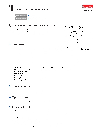
Image preview - the first page of the document

>> Download 2012-TE documenatation <<
Text preview - extract from the document
T      ECHNICAL INFORMATION                                                                                 New Tool

        For Models              2012
        Description             304mm(12") Planer


CONCEPTION AND MAIN APPLICATIONS
 *Only 24kg(52.8lbs), one man can carry it.


                                                                                   430
 *Just fit set plate into drum groove when changing knives.
 *Superb surfacing to uniform stock thicknesses.
                                                                                                                    595
                                                                                                                   (277 with the
                                                                                                                   table folded)


                                                                                                438
  Specifications
                                                                           Continuous Rating
       Voltage (V)         Current(A)             Cycle(Hz)                                            Max. output(W)
                                                                      Input (W)        Output (W)
           100                  14                     50/60             1330              980              1200
           115                  12                     50/60             1330              980              1200
           200                   7                     50/60             1330              980              1200
           220                  6.4                    50/60             1330              980              1200
           230                  6.1                    50/60             1330              980              1200
           240                  5.8                    50/60             1330              980              1200


     No load speed                                Drum speed: 8000/min., Feed speed: 8m/min
     Driving shank (LxWxH)                        Plane blade width: 306mm (disposable blade)
     Max. planing width                           304mm
     Planing depth                                0 to 2.5mm
     Material thickness                           3 to 155mm
     Net weight                                   24kg
     Power supply cord                            2.5m


  Standard       equipment
   Socket wrench ---------- 1         Wrench ------------------ 1
   Hex. wrench ------------ 1         Magnetic holders ------- 2


  Optional       accesories
   Planer blade 306, stand, hood set (dust catcher #410 for woodwork)


  Features       and benefits
   1. Double-edged disposable blade eliminates cut-off(grinding) work.
   2. No need to adjust a blade height, because the blade can be replaced by inserting a set plate into the groove on plane
      cylinder.
   3. 24.0kg light weight and easy to carry even by one person
   4. Support table can be folded in the cases of storage and carrying.
   5. Stainless surface plate is hardly rusted and does not soil surface of material.
   6. Optional accessories such as hood set and dust catcher (for woodwork #419)
      prevents cut chips from spattering and clean work space is assured.
Capacity
1. Max. planing width: 304mm
2. Max. planing depth: under 150mm width; 2.5mm
              150 to 240mm width; 1.5mm
              240 to 304mm width; 1.0mm
3. Material thickness: 3 to 155mm
4. Comparison
(1) Planing test at power 100V

                                        Model                 Makita2012
                  Planing Current / Feed spee
 Material width          depth                d        Current          Feed speed
       300mm                     1mm                    15A              4.6m/min
                                 1mm                    13A              4.8m/min
       240mm
                                 1.5mm                  16A              4.1m/min
                                 1mm                    11A              5.7m/min
       150mm                     1.5mm                  12.5A            5.1m/min
                                 2.5mm                  16A              4.4m/min

  (Note) *Although planing depth is printed as 0 to 2.5mm in catalogs, etc., actual dimension is 0 to 2mm.
(2) Step on the material                                        Step
                                       Material

          Model                                   Makita 2012
  Thickness of the step (mm)                         0.07

  (Note) *Dimensions differ depending on size and weight of the material. (Sample material:150W x 500L mm and
  2kg weight) For a long and heavy material, support it with hands at the beginning and ending of the planing,
  and the thickness nearly to the above dimensions can be gained.
Repair                                                                   Field lead wire
                                                                                            Boss
                                                                                                             Motor housing
1. Replacement of armature field
(1) Before replacement, take apart motor unit. Remove
     four hex. socket bolts which secures motor unit at
     thelower side of the main frame (feed roller side).
     (Same procedure as for 2030N, however roller does                                                Gear
                                                                                                      housing
     not have to be removed.)
(2) Armature can be pulled out without removing V
     pulley. After replacing armature,fasten V pulley
     securely. (V pulley uses a left-handed screw.)                      Gear housing
                                                                         cover
(3) Pass field lead wire under the boss as shown in figure
     1.
                                                                                                                       Figure 1
(4) Use a scale and position the motor unit so that motor
     shaft and drum shaft should be parallelas shown in
     figure 2.                                                                                  Pulley
                                                                                                at drum
                                                                                                 side

                                                                         There should be
                                                                         no clearance

                                                                                                              Scale


                                                                          Motor
                                                                          housing
                                                                                                Pulley at
                                                                                                motor side


                                                                                                Contact it            Figure 2


2. Replacement of drum
(1) Remove plane blade and set plate, and pull out drum from main frame.
(2) Bearing box should be mounted on the main frame so that it's rubber pin faces upper side.
◦ Jabse Service Manual Search 2024 ◦ Jabse Pravopis ◦ onTap.bg ◦ Other service manual resources online : Fixya ◦ eServiceinfo