Service Manuals, User Guides, Schematic Diagrams or docs for : MAKITA 3705-TE
<< Back | HomeMost service manuals and schematics are PDF files, so You will need Adobre Acrobat Reader to view : Acrobat Download Some of the files are DjVu format. Readers and resources available here : DjVu Resources
For the compressed files, most common are zip and rar. Please, extract files with Your favorite compression software ( WinZip, WinRAR ... ) before viewing. If a document has multiple parts, You should download all, before extracting.
Good luck. Repair on Your own risk. Make sure You know what You are doing.
Image preview - the first page of the document

>> Download 3705-TE documenatation <<
Text preview - extract from the document
T    ECHNICAL INFORMATION
      Models No.            3705
                                                                                                          New Tool


      Description           Trimmer

CONCEPTION AND MAIN APPLICATIONS
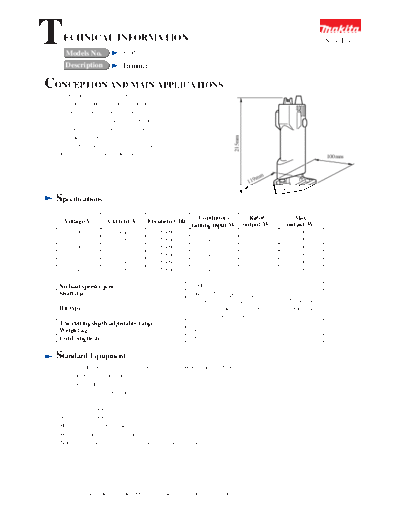
   Unlike the conventional model, wherein the
   bit is directly mounted on the motor shaft,
   this offset-type trimmer can be driven by
   the belt, wherein the bit shaft is mounted
   separately from the motor shaft and the base


                                                                       215mm
   shape near the bit is arranged in triangle
   (angle: 90"), thereby enabling the process
   close to the wall and corner faces.                                                                    100mm


                                                                                      mm
                                                                                119


   Specifications
                                                          Continuous      Rated              Max.
     Voltage(V)       Current(A)      Frequency(Hz)
                                                       ratinng input(W) output(W)          output(W)
         100               4.4             50-60             420           250                300
         115               3.8             50-60             420           250                300
         200               2.2             50-60             420           250                300
         220                2              50-60             420           250                300
         230               1.9             50-60             420           250                300
         240               1.8             50-60             420           250                300

    No load speed(r.p.m)                              23000/min
    Shaft dia                                         6 mm[6.35 for special export]
                                                      The bit with the shaft dia. 6mm (6.35 for special
    Bit-type                                          export) and the cutter edge dia. with below than
                                                      20mm can be installed.
    The cutting depth adjustable range                20 mm
    Weight(kg)                                        1.8
    Cord length(m)                                    2.5


  Standard Equipment
    Guide holder(Straight guide, for mounting the trimmer guide)--- One piece
    Straight guide --- One piece
    Trimmer guide --- One piece
    Template guide --- One piece
    6 mm straight bit --- One piece
    Spanner 17 --- One piece
    Spanner 10 --- One piece
    Hex. wrench 6 --- One piece
    Wrench holder 5-6 --- One piece
    Note that 6 mm straight bit is excluded for special export.


 The standard equipment for the tools shown may differ form country to country
Optional accessories
 Trimmer shoe
  Each bit(Of special accessories[bits]for #700B, the bits with below than 20 mm in cutter edge dia. are included.)
  (Straight bit 8, Straight bit 6, Straight bit 20, U-groove bit, Flash one-face bit 6, Flash both-face bit 6, Wheel-
  mounted flash bit 10, cove beading bit4R, Wheel-mounted guitar-face bit 2, Wheel-mounted two-step
  cove beading bit 2,
  Round-face bit 4R, Wheel-mounted round-face bit 1, Wheel-mounted gingko-face bit 2, Square face bit 60",
  Square face bit 45", U-groove bit 20, Wheel-mounted square-face bit 60"All the parts with shaft dia. 6mm shown
  above and each bit with 6.35(1/4")mm in shaft dia. which can be applied for each bit for export.)


Features And Benefits
 (1) The offset model allows to process even nearest to the wall and corner face. The max. approaching size between
     wall face and bit center is 18.5 mm.
 (2) The fine grip(the grip dia. : 65 mm) enables easy operation.
 (3) Since the belt-driven system will relieve the cutting impact through absorbing into the belt, the endurance
     capacity of the armature can be improved further than the conventional model.
 (4) Since the base mounting bolt is fastened by the hexagon rod wrench, the base can be securely fixed.
Repair
(1) Replacing of poly-V-belt
   Proceed in the following steps.
  1.Use the hexagon rod spanner 6 to remove the hexagon holed bolt M8x11 for mounting the base.
  2.Remove the base from the body.
  3.Use the plus screw driver to remove the pan head screw M4x14 for mounting the belt cover to remove the belt
    cover.
  4.Use the -screw driver to twist the poly-V-belt to outside, set the spanner 10 on the cracked two-face width of
    the drive shaft, shift the poly-V-belt to outside one by one thread while turning the spanner 10 to remove the
    poly-V-belt.
 5. After assembling the new poly-V-belt on all the teeth of V-pulley-3-19 of the armature assembly, set the
    spanner 10 on the cracked two-face width of the drive shaft, engage the poly-V-belt with the V-pulley-3-23 little
    by little while turning the spanner 10 in a way pushing the side face of the wrench 10 against the poly-V-belt.

(2) Replacing of the armature
   After V-belt has been replaced in the orders of 1 to 4 for replacing the poly-V-belt,
  6.Use the -screw driver to remove the holder cap of the carbon brush holder and then remove the left/right
    carbon brushes.
  7. Remove the three pan head screws M4x40 holding the housing.
  8. Use the resin hammer to slightly hammer the drive shaft mounting portion on the motor housing to
     disassemble the housing and then remove the armature.
  9. Insert the V-pulley-3-19 of armature between the vice while protecting the armature with the copper plate etc.,
     turn left the steel plate of the armature by hands to remove the V-pulley-3-19. For assembling, proceed in the
     reverse orders against said disassembling.

(3) When the base depth position adjusting motion became heavy,
     If dust has been entered between the guide pin of the base and the hole of bearing box for housing the guide pin
    during operation, the base motion may become heavy sometimes. In this case remove the base, clean the dust
   and then apply the oil into their engagement.

(4) Endurance capacity of the poly-V-belt
    It may vary depending on the using conditions, but it is normally 140-hr when used in the rated load. If the poly-
    V-belt may be partly damaged, the transmission capacity can be deteriorated. Replace the belt in this case.

(5) Necessary tools
    In addition to the normally attached tools, the plus screw driver, minus screw driver, resin hammer and vice are
    required.
◦ Jabse Service Manual Search 2024 ◦ Jabse Pravopis ◦ onTap.bg ◦ Other service manual resources online : Fixya ◦ eServiceinfo