Service Manuals, User Guides, Schematic Diagrams or docs for : MAKITA BO4561-TE

<< Back | Home

Most service manuals and schematics are PDF files, so You will need Adobre Acrobat Reader to view : Acrobat Download Some of the files are DjVu format. Readers and resources available here : DjVu Resources
For the compressed files, most common are zip and rar. Please, extract files with Your favorite compression software ( WinZip, WinRAR ... ) before viewing. If a document has multiple parts, You should download all, before extracting.
Good luck. Repair on Your own risk. Make sure You know what You are doing.


Image preview - the first page of the document
BO4561-TE


>> Download BO4561-TE documenatation <<

Text preview - extract from the document
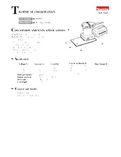
T        ECHNICAL INFORMATION

                                BO4561
                                                                                                            New Tool

          For Models
          Description           Finishing Sander


CONCEPTION AND MAIN APPLICATIONS


                                                                      137 mm
                                                                      (5-3/8")
Model BO4563 is sister version of the existing
Model BO4561 and intended for sanding louvers.
Its brief benefits are;
  *Convenient for sanding narrow louvers


                                                                   10 -15/
                                                                    (3
                                                                     0 16
   by aquare and thinner plate                                                                        8")


                                                                       m ")
                                                                                                 (7-3/


                                                                         m
                                                                                             m
  *With functin of self-dust-collecting                                                187 m
  *The face of pad is velcro type
   to make replacing abrasive paper easy.


    Specifications
         Voltage(V)           Current(A)               Cycle(Hz)      Continuous Rating(W)               Max. Output(W)
                                                                     Input            Output
             220                   0.8                   50/60        160               55                     70
             230                   0.8                   50/60        160               55                     70

       Orbits per minute           14,000 0/min
       Dimension of pad            100mm(3-15/16")X164mm(6-1/2")
       Net weight                  1.0kg(2.2lbs)
       Cord length                 2m(6.6ft)


    Featured       and benifits
     1. Double insulated
     2. See the sheet attached for more information.
 Thickness of pad without abrasive paper                                   Housing shaped ergonomically
 : 4.5mm(3/16")                                                            Easy palm-gripping makes
 As it is about 6.5 mm thick(1/4") if attaching                            operation comfortable.
 #60 Paper to both upper/lower parts,
 suitable for abrasionin narrow space.


                                                                                        Dust Bag
                                                                                        Work area can be kept clean by
                                                                                        function of self-dust-collecting.

                                                  Velcro type for easy
                                                  changing Paper


Repair
When dismantling Housing, remove in advance Base complete, Fan guide, and Fan 63 in this order.
Circuit   diagram
(1) Where Noise suppressor is used


                                                                Switch


                                                                       Insulated connector
                                         1                2
                                                         Black


     Power supply cord

                                             Noise suppressor


                                                                     1 1                     Field

                                                                    Terminal
                                                                    board


(2) Where Noise suppressor is not used


                                                                      Switch


                                             1                  2


     Power supply cord


                                                       1 1
                                                                                                Field
                                                     Terminal
                                                     board
Wiring   diagram


                               Store Lead wire of Power supply cord into Lead holder.
                               ( In case using Noise suppressor, place Lead wire of Noise
                               suppressor under Lead wire of Power supply cord)


                                                    Noise suppressor    Pass Lead wire connecting with Brush holder
                                                                        through here as shown in the Figure.


                                                                                            Pin


                                                                                   Pass Lead wires in Field and Noise
                                                                                   suppressor between Pin and Rib.
                                                                             Rib


                                          Fig. 1


                                                                                     Housing             Housing
     Switch             Switch                                         Lead wire
                                                                                             Lead wire

                                                                                        Fig. 4
                   Insulated                Insulated
                                            connector                       Place Lead wire lower than the
                   connector                                                meeting face of Housing.

               Fig. 2                  Fig. 3


              When you use Noise suppressor, place Insulated connector under Switch
              on its side as shown in Fig. 3 to prevent it from interference with Switch


◦ Jabse Service Manual Search 2024 ◦ Jabse PravopisonTap.bg ◦ Other service manual resources online : FixyaeServiceinfo