Service Manuals, User Guides, Schematic Diagrams or docs for : MAKITA DC1801-TE
<< Back | HomeMost service manuals and schematics are PDF files, so You will need Adobre Acrobat Reader to view : Acrobat Download Some of the files are DjVu format. Readers and resources available here : DjVu Resources
For the compressed files, most common are zip and rar. Please, extract files with Your favorite compression software ( WinZip, WinRAR ... ) before viewing. If a document has multiple parts, You should download all, before extracting.
Good luck. Repair on Your own risk. Make sure You know what You are doing.
Image preview - the first page of the document

>> Download DC1801-TE documenatation <<
Text preview - extract from the document
T        ECHNICAL INFORMATION                                                                               New Tool

            For Models           DC1801
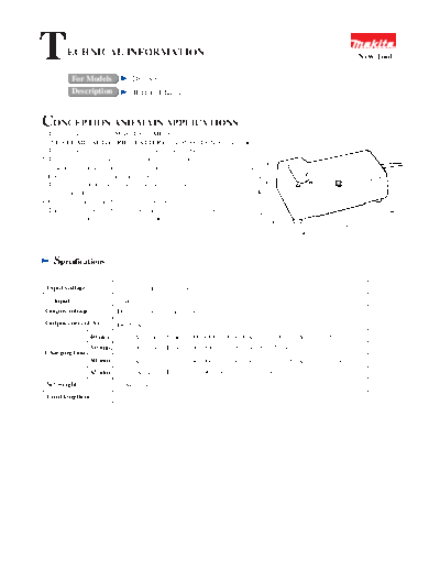
            Description          Battery Charger


CONCEPTION AND MAIN APPLICATIONS
1. This charger can charge MAKITA Ni-MH batteries
   (NICKEL METAL HYDRIDE BATTERY) and MAKITA Ni-Cd batterie.             s
   This charger can charge all voltages from 7.2V to 18V.
2. This charger has a trickle charging function, by which fully-charged
   batteries will be kept fully charged while left in charger.           78mm
3. Even a heated battery after use can be left in the charger.          (3-1/8")
   This charger automatically starts charging the battery
   afer cooled down.
4. Charging condition is displayed by green or red light.


                                                                       10 /8")
                                                                        (4-
                                                                         5m
   The light indicates ready to charge, charging, charging complete,

                                                                            1
                                                                             m
   delay charge (too hot) and defective battery.
                                                                                                       201mm
                                                                                                             16")
                                                                                                      (7-15/


    Specifications

  Input voltage           120V,220-240V,230-240V
    Input                  60W
 Output voltage           DC7.2V,9.6V,12V,14.4V,18V
 Output current(A)        DC 2.1A
                  40 min. for 1.3Ah battery(Battery 7000,9000,9100,9100A,9120,1200,1200A,1210,1220)
                  50 min. for 1.7Ah battery(Battery 7001,9001,9101,9101A,1201,1201A)
 Charging time
                  60 min. for 2.0Ah battery(Battery 7002,9002,9102,9102A,9122,1202,1202A,1222,1422,1822)
                  65 min. for 2.2Ah battery(Battery 7033,9033,9133,1233,1433,1833)
 Net weight               0.48kg(1.06lbs)
  Cord length(m)          2m(6.6ft)
 Features     and benefits

 How to charge
 1. Computer control
    Computer deducts the completion of charging and controls charging current.
 2. Switching power source method
    First,input electricity is converted to high-frequency current of approximately
    one hundred kHz. And the voltage is transformed innto the battery voltages
    by the high-frequency transformer.
    The charger can be designed smaller and lighter than using the general transformer
    with this method.
 3. Constant current charging
    Charging current will be kept stable, so that the change of the battery
    can be detected.
    (See the "1. minus delta V" of Method of stop charging)
 4. Trickle charging function
    See "CONCEPT AND MAIN APPLICATIONS" .


 Method of stop charging
 DC1801 has four different methods of stop charging.
 Each of methods will work individually.(whichever method comes first will stop charging.
 1. minus delta V
    Charging will be stopped by the detection of the drop of the battery voltage.
    See (1) of chart below.
 2. delta T
    Charging will be stopped by the detection of the rise of the battery temperature.
    See (3) of chart below. (for the batteries with 4 terminals only)
 3. T
    Charging will be stopped by the detection of the upper limit of the battery temperature.
    See (2) and (3) of chart below.
    The upper limits of the battery temperature are 45 degree C. for 1.3Ah batteries
    and 60 degree C. for 1.7, 2.0 and 2.2Ah batteries.
 4. Timer
    Charging will be stopped by the length of charging time as a supplementary method.


                                                                           minus delta V

                                                                              T
                            (1)
Battry Voltage
Temperature
                                   (2)
                                                                             delta T
                                   (3)


                                  Completion of Charging                      Charging Time


              Line (1)   shows Battery Voltage.
              Line (2)   shows Battery Temperature of Heated Battery.
              Line (3)   shows Battery Temperature of Nomal Battery. Charging is stopped at delta T.
       Note : Comparing line (2) and line (3) , you can find the point of stop charging before
              completion of charging on line (2).
Repair                                                                                                circuit board

In case of damage of the varistor or fuse, please carry out the repairing as follows,
   then it is not required to change the circuit board.

  1. How to check the damaged varistor
     In case of the following condition, the varistor has to be changed.                         varistor
                                                                                          VS2
     1) The surface of varistor is broken.                                                            Use with the circuit board
     2) The circuit board near varistor or the inside of charger case is sooty.                       No.6312498 and 6312829
     3) In case of breakage of fuse, also the varistor can be defective.                              only
     4) In case of connection of the fast charger with double voltage power
        source of rated voltage for the fast charger, the varistor can be damaged.
                                                                                           Power Supply Cord
     5) However, the circuit board has to be changed in case that only
        the fuse is damaged. (the varistor is in order)

                                                                                                                  varistor


  1. How to dismount and mount the varistor                              circuit board
     1) Take off damaged varistor soldered on the circuit board, with soldering iron.
     2) Solder the new varistor on the circuit board with soldering iron,
        and then the extra lead wire from the varistor has to be cut by nipper.                                   Fuse


                                                                                The overhang length must be under 3mm


  1. How to dismount and mount the fuse
     1) Take off damaged fuse soldered on the circuit board, with soldering iron.
     2) Solder the new fuse on the circuit board with soldering iron,
        and then the extra lead wire from the fuse has to be cut by nipper.
                                                 Fuse


                                                    The overhang length must be under 3mm by cutting the extra.


Interchangeability

The following spare parts have an interchangeability with the existing DC1411.

 Vinyl Cord
 Tapping Screw M4 x 25
 Varistor
 Fuse (only P/N 652727-4)

The spare parts other than the above mentioned have no interchangeability.
◦ Jabse Service Manual Search 2024 ◦ Jabse Pravopis ◦ onTap.bg ◦ Other service manual resources online : Fixya ◦ eServiceinfo