Service Manuals, User Guides, Schematic Diagrams or docs for : MAKITA HK0500-TE

<< Back | Home

Most service manuals and schematics are PDF files, so You will need Adobre Acrobat Reader to view : Acrobat Download Some of the files are DjVu format. Readers and resources available here : DjVu Resources
For the compressed files, most common are zip and rar. Please, extract files with Your favorite compression software ( WinZip, WinRAR ... ) before viewing. If a document has multiple parts, You should download all, before extracting.
Good luck. Repair on Your own risk. Make sure You know what You are doing.


Image preview - the first page of the document
HK0500-TE


>> Download HK0500-TE documenatation <<

Text preview - extract from the document
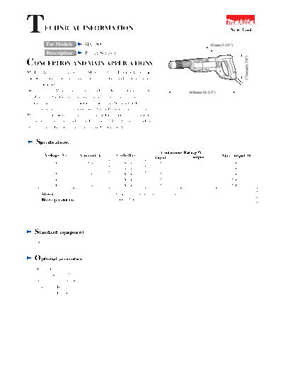
T        ECHNICAL INFORMATION                                                                                  New Tool

          For Models             HK0500                                                              83mm(3-1/4")

          Description            Power Scraper


                                                                                                                      174mm(6-7/8")
CONCEPTION AND MAIN APPLICATIONS
Model HK0500 exclusively for SDS-Plus Bit , developed for fine
chipping works, such as tearing up tiles, joints, and mortar in re-
construction sites.
 We have put Motor laterally and made the Barrel thickness to be                          468mm(18-1/2")
suitable for gripping so that tile tearing works may be easier. In
Chuck structure, one-touch sliding system has been applied, which
you can attach only by inserting Bit and searching grooves.
Moreover, your fingers will not be exhausted in continuous operations
 owing to Large switch and Large D-shape handle. At the top end, a
very effective dust-proof cap with lip has been applied.


    Specifications
                                                                          Continuous Rating(W)
         Voltage (V)         Current(A)          Cycle(Hz)              Input            output            Max. output(W)
              100                 5.8                 50/60              550              260                   500
              115                 5.0                 50/60              550              260                   500
              220                 2.6                 50/60              550              260                   500
              230                 2.5                 50/60              550              260                   500
              240                 2.4                 50/60              550              260                   500
        Motor                                    Series commutator motor ( 72 type 25 )
        Blows per minute                         2000~3500 bpm


    Standard        equipment
     Scaling chisel


    Optional        accesories
     Bull point 14-250
     Cold chisel 20-250
     Scaling chisel 38-200
     Grease for Bit
     Grease for Hammer
 Shape for easy use                                    Low Vibration                           Whole plastic body
The length and shape suitable for tile tearing ,                                               If Bit touches electric wires in the
putting Motor laterally.                                                                       wall, electric shock is rarely conveyed
                                                                                               to a worker because the whole outer
                                                                                               surface is covered by plastic.


                                                                                                 With dial of variable/stepless speed
                                                                                                You can do finer chipping works, and
                                                                                                operate the dial, pulling Trigger.


                                                      Barrel part easy to be gripped
        Improved Dust-proof
                                                     Very comfortable to grip because of its     Large L-shape handle
       Owing to applying a dust-proof                proper thickness and length ( 58x100mm,
       cap with lip, it is prevented that                                                       Large and round Handle shape is easy
                                                         2-1/4" x 3-15/16" )
       dusts enter from the top end.                                                            to grip.


                                                                                                 Large Trigger switch
     Light weight
                                                                                                Your fingers will not be exhausted
    MAKITA #HK0500:
                                                                                                even after a long time operation.
    3.1kgs (6.8 lbs)
                           One-touch sliding chuck
                          By only inserting Bit and searching
                                                                                                 Thick commutator
                          grooves, you can install Bit.
                                                                                                Effective thickness of Segment in
                                                                                                Commutator has been made to be as
                                                                                                twice big
            Tough body                                       Bit can be fixed at 12 levels       as that of #HK1810. Also, it is
                                                             of degreed position.               protected from radiant heat and dust
           The strength is enough to bear if you
           use it gouging like a bar.                       The strength is enough to           particles by
                                                            bear if you use it gouging
                                                            like a bar.
                                                                                                    Handle cover
Repair
1. Repair of Armature
   Disassembly:
   1) Remove Tapping screw4x18(6 pcs) , Handle cover,
     and Carbon brush. (See Fig. 1)


                                                            Tapping screw M4x18


                                                                         Fig. 1
  2) Remove Tapping screw5x20 (4pcs) , and separate                                                        Tapping
                                                                                                           screw5x20
    Clunk housing from Motor
     housing. (See Fig.2)


                                                                                                          Clunk
                                                                                                          housing cover
                                                                                                          Motor housing


                                                                                           Fig. 2
                                                                                                           Countersunk
   3) Remove Countersunk head screwM4x12(2pcs) and
                                                                                                           head screw
     Armature. ( See Fig.3)                                                                 Armature       M4x12


                                                                                  Fig. 3


                                                                                               Retaining ring
Assembly:
                                                                                               (axis) S-12
1) After installing Bearing retainer68 and Flat washer12,
     attach Ball bearing                                                                       Ball bearing 6201 DDW
    6206201DDW. Then install Retaining ring (axis) S-
     12. ( See Fig.4)                                                                           Flat washer 12


                                                                                               Bearing retainer 68

                                                                                               Armature


                                                                                  Fig. 4
2. Repair of Chuck
    Disassembly:
   1) Lower chuck cover and remove Cap37 (See Fig.5)
      Then , remove Chuck cover, Compression spring38                                                     Chuck cover
                                                                      Cap 37
     and Spring guide ( See Fig.6)
   2) Remove Leaf spring 26 from Chuck ring and remove                    Chuck cover
                                                                                                            Compression
     Pin( See Fig.7).                                                                                       spring 38
     Remarks: You can remove Leaf spring easily by
     Retaining ring plier .                                                                                 Spring guide


                                                         Fig. 5


                                                                                        Fig. 6
  3) When removing Chuck ring, Steel ball7.0, Spring                                       Leaf spring 26
    guide and Compression spring38 will come off. (See
    Fig.7)                                                                                Chuck ring

                                                                                           Pin 8
                                                                                           Spring guide


                                                                                           Compression
                                                                                          spring 38
                                                         Steel ball 7.0


                                                                                         Tool holder


                                                           Fig. 7


Assembly
  In attaching Pin8, you need to lower Spring guide
  (See Fig. 8).
                                                                                        Spring guide


                                                                                                       Pin 8


                                                                     Fig. 8
3. Repair of Clunk housing
                                                             Tapping screw 4x18
   Disassembly:
   1) Remove Tapping screw4x18(2pcs), and pull out
     Clunk housing cover. (Fig.9).


                                                           Clunk housing cover


  2) Remove Tapping screw4x16(4pcs) and Clunk cap.
    (Fig.10)                                                            Fig. 9


                                                                                        Tapping screw 4x16


                                                                                        Clunk cap


                                                                                        O Ring 53
  3) Remove Retaining ring (hole) R-38 and pull out Tool
    holder. (Fig.11)
                                                                                        Piston


                                                                        Fig. 10


  4) Take out Piston from Clunk housing. (Fig.10)


                                                                                  Retaining ring (hole) R-38


                                                                                  Clunk housing


                                                                                  Tool holder


                                                                        Fig. 11
Assembly
  1) After attaching Flat washer27 to Clunk housing,
    install Oil seal 30. ( See Fig.12)
                                                                                 Flat washer 27
                                                             Oil seal 30


  2) After attaching Piston to Clunk shaft, install Tool         Clunk housing
    holder. ( Fig.10)                                                  Fig. 12
    NOTE: Check that Flat washer 27 is not inclining and
    is in a position shown in
      Fig. 12 .


  3) Using Jig (1R 232), install Ring27, Polyurethane
    washer28 and Ring27 in this
     order. ( See Fig. 13)
                                                                                        Jig (1R232)


                                                                                      Ring 27

                                                                                       Polyurethane washer 28


                                                                                       Ring 27
  4) Check if O Ring 53 is attached to Clunk cap or not. (
    See Fig.10)


                                                                    Fig. 13
4. Repair of Tool holder
  Disassembly:
  1) Insert SDS-plus with its end ahead , and pull out
      Striker by pressing Impact bolt.
     ( See Fig. 14)


                                                                                              Tool holder                Striker


                                                                                              Fig. 14


  2) Put a thin   driver into hole of Tool holder, hit it by
    plastic hammer, and remove
     Ring spring 21 from grooves. ( See Fig.15)


  3) Inserting a thin round rod into the end and hitting it by
     Plastic hammer, take the                                                                              Tool holder
    following items out of Tool holder;
     Impact bolt, Flat washer13, O Ring 15,                                                   Fig. 15
     O Ring case, Ring spring21
      ( See Fig. 16)


                                      Tool holder                Flat washer 13       O Ring case       Ring spring 21


                                                                        Impact bolt         O Ring 15

                                                     Fig. 16
Assembly
 1) Check that O Ring 11 is put in O Ring case.


 2) After making Flat washer13, O Ring 15 and O Ring
                                                                        Striker
    case pass through Impact bolt, press them into Tool
    holder. (See Fig.17)
    At that time use Striker as a jig putting up-side-down.                                                    O Ring 11
                                                                 O Ring case


                                                                   O Ring 15

                                                              Flat washer 13
    NOTE: Use O Ring 16 of Striker after removing. Be
    careful about the order of                                                                               to Bit side
                                                                 Impact bolt
    each part and the attaching direction of Impact bolt.


                                                                                              Fig. 17

  3) In installation, exchange Ring spring 21 for a new
    one.


                                                                                                     Ring spring 21

  4) Insert Ring spring21 in Tool holder by ? driver, etc.,
    use Striker as a jig in the
    same way as 2), and then place Ring spring 21 into                                                  Groves in
    grooves of Tool holder. ( See Fig. 18)                                                              Tool holder


                                                                                             to Bit side


  5) Being careful of the attaching direction of Striker,
    press it into Tool holder. ( See fig.19)                                   Fig. 18


                                                                                   Striker


                                                                                   Impact bolt


                                                                               to Bit side


                                                              Fig. 19
5. Repair of Spiral gear
   Disassembly
                                                                                Tapping screw 4x16
  1) Remove Tapping screw4x16 and Gear cover. ( See
     Fig.20)
                                                                                Gear cover


                                                                        Jig (1R238)
                                                                                Ball bearing 6200LLB
 2) Use Jigs, 1R232 and 1R238, shown in Fig.20, press                           Clunk shaft
    out Clunk shaft by Arbor press.


                                                                                   Spiral bevel gear 41


                                                                                  Clunk housing


                                                                              Jig (1R232)
                                                           Fig. 20

                                                                                Clunk shaft


Assembly
 1) Attaching Ball bearing6002LLU to Clunk housing,                                     Retaining
    install Retainer ring(hole) R- 32. ( See Fig. 21)                                   ring(hole) R-32
                                                                                        Ball bearing
                                                                                        6002LLU
                                                                                         Oil seal 15
 2) Install Oil seal15 in Clunk housing using Jig 1R249.
    At that time put it approx.
    1mm deeper than end surface. ( See Fig.21)
                                                                      1.0


                                                            Fig. 21
 3) Attach Clunk shaft.                                                                     Gear cover


                                                                                      Ball bearing 6002LLU

 4) Fixing Clunk shaft steadily by Jig1R216, press in
                                                                                         Spiral bevel gear41
    Spiral gear41 and Ball bearing6200LLB . After that,
    install Gear cover. (See Fig.22)
                                                                                    Clunk shaft


                                                            Fig. 22                   Jig(1R216)
6. Grease
 [ Grease exchange]
 In exchanging Carbon brush, exchange Grease also.
 1) Drive the Machine for several minutes for warming.
 2) Referring to the above mentioned (2) Chuck repair and (3) Clunk housing, remove Clunk cap.
 3) Directing the Machine top end upward, collect Grease in Clunk room, wipe it away with a cloth, and pour in 10 cc of
     MAKITA grease R No.00.

    NOTE: If you put Grease more than the defined quantity, a trouble such as wrong striking may occur. So, be careful
    not to pour too much.

[ Place to apply Grease ] ( :applying place)
Apply Grease to the following positions to prevent early abrasion and being burnt
down.


1) Where MAKITA Grease is to be applied
    Impact bolt:
                 O Ring,
                 X Ring,
                 All around Impact bolt


     Striker:
                  O Ring,
                  All around Striker


     Piston:
                   O Ring,
                   All around Piston
     Rod :
                    Inside of attaching hole
     O Ring case:
                    All around both inner/outer
                    diameters of O Ring


     Oil seal 15
     Oil seal 30


     Tool holder:
                    All around the part shown
                    in the illustration.


2. Where MAKITA Grease R No.1 is to be applied
     Spiral bevel gear 41: Teeth surface


3. Where MAKITA Grease N No.2 is to be applied
     Tool holder: Pin hole,
                  Steel ball hole
Wiring    diagram
[ Where Insulated connector is used ]

                                                                                                 Field

                                 Switch
                                                      Orange
               P1
                              3            2


         Power supply cord
                                   Noise suppressor


                                                                                     Black
               P2
                                                            White


                                      Insulated connector
                                                                                 Controller
NOTE: In some areas, Noise suppressors are not used.


[ Where Terminal black is used ]


                                                                                                    Field
                                                                       Orange
                                  Switch
                                                            Ckoke coil
                                                Orange
                P1
                             3             2


      Power supply cord      Noise suppressor                            White
                                                                                                                                  Purple
                                   Clear                               Earth teminal

                                                                         to Field steel core                         Ckoke coil
                                                               Clear
                P2
                                                                                      Black
                                  Terminal block
                                                                                                            Purple
                                                               Insulated connector
                                                                                               Controller
NOTE:
*In some areas, Noise suppressors are not used or Two-foot Noise suppressors are used.
* In other areas, Choke coils are not used.
Notes   in assembly
(1)Field leas wire (Black)

                             Handle
                                                                                       See to it that Field lead wire
                                                                                       willnot run on the diagonal line
                                                                                       part in the Illustration.


                                                                                         Do not make Lead wire
                                                                                         loosened here.


(2) Within Handle


                                                                Place Choke coil lead wire here ,
                                                                folded as shown in the illustration.


         Be careful so that Lead
         wires ( Orange and
         Purple)for connecting
         Brush holder may not
         slacken toward the
         Commutator side.                                                                      Terminal block (if used)
                                                                                               When using Insulated
     Store Field lead wire                                                                     connector
    (White) and Lead wire for
    Earth relay ( if used) after
                                                                                                  place it around
    having attached Brush
                                                                                                  here.
    holder.

                                                                                                   Noise suppressor (if
     Do not store Varnished
                                                                                                   used)
     polyester tube (for protection
     of White filed lead wire
     andLead wire for earth relay,
     if used ) into Lead holder.
                                   Store Lead wire into
                                   Lead holder.         Insulated connector for
                                                        connecting Earth lead wire
                                                        ( if used )


◦ Jabse Service Manual Search 2024 ◦ Jabse PravopisonTap.bg ◦ Other service manual resources online : FixyaeServiceinfo