Service Manuals, User Guides, Schematic Diagrams or docs for : MAKITA HR2010-TE
<< Back | HomeMost service manuals and schematics are PDF files, so You will need Adobre Acrobat Reader to view : Acrobat Download Some of the files are DjVu format. Readers and resources available here : DjVu Resources
For the compressed files, most common are zip and rar. Please, extract files with Your favorite compression software ( WinZip, WinRAR ... ) before viewing. If a document has multiple parts, You should download all, before extracting.
Good luck. Repair on Your own risk. Make sure You know what You are doing.
Image preview - the first page of the document
>> Download HR2010-TE documenatation <<
Text preview - extract from the document
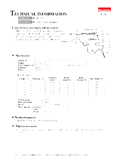
TECHNICAL INFORMATION HR2010
Product
Models No.
Description 20mm Rotary Hammer
CONCEPTION AND MAIN APPLICATIONS 287mm (11-1/4")
HR2010 is designed to belooked stronger structure,
with traditional "D" handle and some aluminium parts.
In overhead horizontal operations, HR2010 has
214mm (8-3/8")
great performance in drilling 6mm-12mm holes.
91mm (3-5/8")
Specifications
Dimension 287mmx214mmx91mm (11 4/1"x8 3/8"x3 5/8")
Weight 3.1Kgs (6.8lbs)
Power Supple Cord 5m(16.4ft) (Note:4m=12ft for China and European Countries)
Insulation Double Insulation
Motor AC universal motor (72mm)
Motor Features
Frequency Rated Rated
Voltage (V) Amperage (A) Max. Output(W)
(Hertz) Input(W) Out-put(W)
100 6.3 50/60 600 310 480
110 5.5 50/60 600 310 480
115 5.5 50/60 600 310 480
220 2.9 50/60 600 310 480
230 2.7 50/60 600 310 480
240 2.6 50/60 600 310 480
No load speed 0-900rpm
Blows per minute 0-4000
Bit size 10mm(3/8") SDS-Plus only
Max.Capacities Concrete 20mm(13/16")
Steel 13mm(1/2")
Wood 24mm(15/16")
Standard equipment
Depth Rod, Side Grip, Plastic Carrying Case
Optional accessories
Drill Chuck Assembly, Chuck Key S13, Holder Driver, Dust Cup 5, Blow-out Bulb, Lock Nut Wrench 28, Dust
Collector Set
The standard equipment for the tools shown may differ from country to country.
HR2010
Shorter overall length makes weight
Center closer to handle, and this
makes handling easier,
with torque-limiter
electrical variable switch makes
centering job easier
rotato change ring to
put on or off bits
grip can be fixed at any position;
turn clockwise to fasten
360 degree adjustable grip/
counter-clockwise to loosen
stronger handle design
Repair
(1) Disassembling and assembling O ring 10
1-1. Disassembling of chuck
Change ring cover
Use the minus screw driver just like pushing up to disconnect
Leaf spring
the cap 37 as shown on the right figure.
Pull out the change ring cover.
Strongly pull out the change ring to disconnect it. If hard to
disconnect, place the minus screw driver between clearance
of leaf spring, expand the leaf spring just like twisting the
driver, and then pull out it. It is fixed by steel ball and leaf
spring.
Cap 37
Disconnect the roller 7(2 pieces).
Change ring
Roller 7
1-2. Assembling of chuck
Grease the MAKITA grease R No. 1 on the roller 7 and then assemble it.
Press
2-1. Disassembling of barrel
Remove the hexagon socket bolt M5x20 and then remove
the barrel. Tool holder
Use the arbor press to press the top of tool holder to
Trace of pusher pin
remove it.
2-2. Assembling of barrel
Assemble in a way that the trace of pusher pin shown on
the right figure comes at name plate side.
3-1. Disassembling of impact bolt
Use the screw driver to shift the impact bolt in the direction of tool holder edge as shown on the bottom-
right figure.(in the direction of arrow 1)
Use the resin hammer to slightly hammer the tool holder as shown on the bottom-right figure to remove
the four points of steel ball 5 and 6.
Use the sharpened-edge tool like an eyeleteer to pull out Steel ball 5 and 6
Tool holder O ring 11
the O ring 11 as shown on the bottom-right figure. For
easy disconnection, use the eyeleteer while 5 mm around
of sharpened-edge tool edge is being bent by 90"around.
Use the driver edge to disconnect(push) the impact
bolt.(in the direction of arrow 2
Impact bolt
Press
3-2. Assembling of impact bolt
Use the screw driver to insert the impact bolt into the tool
holder.
Use the sharpened-edge tool to insert the O ring 11 into the
groove of the tool holder. Move the impact bolt in the direction O ring 11
of arrow to check if O ring 11 cannot be disconnected.
Before placing the steel ball 5 and 6 in the tool holder, grease Impact bolt
Steel ball 5 and 6
into the hole so that the steel ball cannot drop and the tool
holder can be easily set. Tool holder Arrow
Flat washer 26
4-1. Disassembling of torque limiter Tool holder
Use the circle clip plyer to disconnect the circle clip(shaft)S- Circle clip
Spiral bevel (shaft)S-26
26 and then remove the spiral bevel gear 33, clutch cam and gear 33
compression spring 31.
Clutch cam
If hard to disconnect the parts, shift the flat washer 26 away
from the circle clip groove since it is housed in said groove. Compression
spring 31
4-2. Assembling of torque limiter (Spiral bevel gear 33 side)
Use care of direction of clutch cam when assembling the
torque limiter.
Engage the protruded portion with the spiral bevel gear 33
(Compression spring 31 side)
while supporting the compression spring 31 by holding the
dent face. This protruded face is almost
the same in size as the one of Direction of tool holder edge.
cam of spiral bevel gear 33.
5-1. Disassembling of crank
To disassemble the handle set, disconnect the two points of pan head screw M5X25 connected on the
crank housing complete and then disconnect the tapping Pan head screw M5x25
screw PT5x25 connected on the motor housing complete.
Crank cap
To disassemble the motor housing complete, disconnect the
hexagon holed bolt M5x45 connected on the gear housing Crank housing
complete
complete and crank housing complete.
Separate the crank housing from the gear housing. Gear housing complete
Use the lock nut wrench 28 to disconnect the crank cap. Motor housing complete Handle set
Tapping screw PT5x25
Hexagon holed bolt M5x45
Crank cap
Push the crank shaft from the crank cap side to pull out it
O ring 36
as shown on the bottom-right figure.
Since the ball bearing 6001, ball bearing 6002, helical gear
43 and helical gear 29 are inserted by pressing, use the arbor Crank housing
complete
press to pull out them.
At this time use care not to miss the flat washer 8.
Spiral bevel gear 29
Crank shaft
Ball bearing 6001
Ball bearing 6002
5-2. Assembling of crank Flat washer 12
Circle clip
For assembling, follow in the reverse order against (shaft)S-15
Helical gear 43 Helical gear 29
disassembling.
Flat washer 8 Flat washer 8
Gear housing complete
6-1. Replacing of armature
Disconnect the holder cap from the motor housing complete
to pull out the carbon brush.
Use the resin hammer to disconnect the one body of armature
complete and gear housing complete from the motor housing
complete.
Pull out the armature complete while holding the gear
housing complete. Brush holder
Motor housing complete
6-2. Assembling of armature Press
Assemble the ball bearing 6000 and oil seal 12 on the gear Gear housing complete Ball bearing 6000
housing complete before inserting the armature.
Oil seal 12
Note) If one body assembled with ball bearing and oil seal is
inserted into the armature, the oil seal cannot be
completely inserted and it may cause oil leaking.
Armature complete
(2) Lubricating points
To avoid abrasion at earlier stage and heating damage, apply the MAKITA oil XLD on the points shown
below.
1) O ring on the impact bolt
O ring and groove
2) Outer circumference of the striker and O ring
3) Outer circumference of piston and O ring Outer circumference O ring and groove
Outer circumference
O ring and groove
To avoid abrasion at earlier stage and heating damage, use the MAKITA grease R No. 00 to grease on the
points shown below.
1) Outer circumference of pin5
Outer circumference
2) Each teeth face of Helical gear 43, Helical gear 29, spiral Teeth face
bevel gear 9 and spiral bevel gear 33 Teeth face
3) Cam of spiral bevel gear 33 and cam of clutch cam Teeth face
Both edges
4) Flat washer 8 Both edges on flat washer 23 Cam
Cam
5) Lip face of oil seal 20
6) Needle bearing 810
Lip face
(3) Necessary tools
1) + screw driver
2) - screw driver
3) Arbor press
4) Resin hammer or wooden hammer
5) Radio cutting plyer
6) Sharpened-edge tool like an eyeleteer
7) O ring inserting jig
◦ Jabse Service Manual Search 2026 ◦ Jabse Pravopis ◦ onTap.bg ◦ Other service manual resources online : Fixya ◦ eServiceinfo