Service Manuals, User Guides, Schematic Diagrams or docs for : MAKITA MT601-TE

<< Back | Home

Most service manuals and schematics are PDF files, so You will need Adobre Acrobat Reader to view : Acrobat Download Some of the files are DjVu format. Readers and resources available here : DjVu Resources
For the compressed files, most common are zip and rar. Please, extract files with Your favorite compression software ( WinZip, WinRAR ... ) before viewing. If a document has multiple parts, You should download all, before extracting.
Good luck. Repair on Your own risk. Make sure You know what You are doing.


Image preview - the first page of the document
MT601-TE


>> Download MT601-TE documenatation <<

Text preview - extract from the document
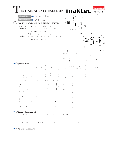
T     ECHNICAL INFORMATION
    Model No.                 MT600, MT601                                                W
                                                                                                                      PRODUCT
                                                                                                                        P1/9
                                                                                          L
    Description               Drill 10mm (3/8")
CONCEPT AND MAIN APPLICATIONS
   New power tool series from MAKITA                                                                    H
   * MT600 : 1. Less expensive, but service life is long as                             MT600
                the existing models.
             2. Easy to repair construction                                                                      W
   * MT601 : Equipped with keyless drill chuck in addition                                                        L
              to the above features.                                                                            W

                                                                                                                             H
                                                                                                     MT601
                                                                                Dimensions : mm ( " )
                                                                           Model No.      MT600              MT601
                                                                           Length ( L ) 236 (9-1/4)         242 (9-1/2)
                                                                           Width ( W )           71 (2-13/16)
                                                                           Height ( H )         194 (7-5/8)
  Specification
                                                                             Continuous Rating (W)
       Voltage (V)           Current (A)           Cycle (Hz)                                               Max. Output(W)
                                                                            Input           Output
        * 110                3.3              50 / 60                        350              180                 230
          220                1.7              50 / 60                        350              180                 230
        220 / 230            1.6              50 / 60                        350              180                 230
        230 / 240            1.5              50 / 60                        350              180                 230
         * The data with 110V is available only for MT600.

    Model No.                                MT600                       MT601
    No load speed : (min -1= rpm)                          0 - 2,500
    Keyless chuck                                No                      Yes
    Chuck ability : mm ( " )                          1.5 - 10 (1/16 - 3/8)
    Drilling            in Steel                          10 (3/8)
    capacity : mm ( " ) in Wood                           25 (1)
    Reverse switch                                           Yes
    Protection from electric shock                     by double insulation
    Cord length : m ( ft )                                2.0 (6.6)
    Net weight :Kg (lbs )                                 1.4 (3.1)


 Standard equipment
     * Chuck key ................................... 1 pc. (available only for MT600)


    < Note > The standard equipment for the tool shown may differ from country to country.


 Optional      accessories
Features          and benefits                                                                                       P2/9
                                                            Keyless drill chuck
                                                            for easy changing of
                                                            drill bits                    Dust proof ball bearing,
                                                                                          mounted to spindle

                                                            MT601


   Dust proof ball bearing,                       Body, assembled with
   mounted to spindle                             machine screws for easy
                                                  repairing.

                                    MT600
                                                                                   Variable switch
                                                                                   with R/L change lever


                                                                                          Lock on button for
                                                                                          continuous operation


                                                                               Distinctive orange color
                                                                             for MAKTEC series model
          Body, assembled with                                                     ( both models )
          machine screws for easy
          repairing.
                                                                            Dust protecting washers are
                                                                            mounted to the ball bearings
                    Variable switch                                         of armature.
                    with R/L change lever                                   ( both models )


                              Lock on button for                         Cylindric-constructed Motor housing
                              continuous operation                       with high rigidity
                                                                         ( both models )

Comparison            of products
 Model No.                                            MAKITA                         Competitor A
                                            MT600        MT601          6410           Model A
 Power input : W                                   350                   350             450
 No load speed : (min -1= rpm)                 0 - 2,500              0 - 2,200        0 - 2,500
 Keyless chuck                              No            Yes            Yes             Yes
 Chuck ability : mm ( " )                      10 ( 3/8)               10 ( 3/8)       10 ( 3/8)
 Drilling            in Steel                  10 (3/8)                10 (3/8)        13 (1/2)
 capacity : mm ( " ) in Wood                   25 (1)                  25 (1)          25 (1)
 Reverse switch                                    Yes                   Yes             Yes
 Protection from electric shock                          by double insulation
 Cord length : m ( ft )                        2.0 (6.6)               2.0 (6.6)        2.5 (8.2)
       Length : mm                      236              242            250               256
 Dimensions


                (")                    (9-1/4)          (9-1/2)       (9-7/8)          (10-1/8)
       Width : mm                                  71                    63                64
                (")                            (2-13/16)               (2-1/2)           (2-1/2)
       Height : mm                               194                    183               207
                (")                             (7-5/8)               (9-1/4)           (8-1/8)
  Net weight :Kg (lbs )                         1.4 (3.1)            1.2 (2.7)          1.5 (3.3)
Repair                                                                                                            P3/9
< 1 > Lubrication
     Apply MAKITA grease N. No.1 to the following portions marked with black triangle to protect
     parts and product from unusual abrasion. See Fig. 1.
         7. Helical gear 39 : approx. 3.5g (0.12 oz)
        13. Armature, gear portion : approx. 3.5g (0.12 oz)


                                                    7                    13
                                                        Fig. 1
< 2 > Removing drill chuck
      Firmly hold No.1R139 "Drill chuck extractor" with vise. And lock spindle with the drill chuck extractor.
      Hold hex wrench with drill chuck firmly.
      Strike the hex wrench with hammer so that the drill chick turns anti-clockwise. See Fig. 2.
      So drill chuck can be removed from spindle.

                                                   No.134873-0 Bit adaptor

                                                No.1R231 Hex shank bit M8


                                                                            1R139 Drill chuck extractor

                                                         Fig. 2
< 3 > Mounting drill chuck
      Firmly hold No.1R139 "Drill chuck extractor" with vise. And lock spindle with the drill chuck extractor.
      Hold the repairing tools in Fig. 3A, with drill chuck as illustrated in Fig. 3. And turn torque wrench clockwise.

                                   
                                   Pre-set the fastening torque of the torque wrench with 15 - 20 N.m, when assembling.
      No.1R220 Ratchtet head

                                1R231                                   1R231
                                1/4" Hex. Shank Bit M8                  1/4" Hex. Shank Bit M8


   Torque
   wrench               No.1R222
                        Socket adaptor
                                          No.134873-0
                                          Bit adaptor
                     Fig. 3A                                                     Fig. 3
Repair                                                                                                         P4/9
< 4 > Disassembling gear section
     (1) After removing drill chuck, separate gear housing from motor housing by unscrewing 3 pcs.
         of pan head screws M4x18. See Fig. 4.
         Tap the edge of gear housing with plastic hammer. So, helical gear 39 section can be removed from
         gear housing. See Fig. 5.


              Ggear            Ggear
              housing          housing cover
                                                                                  Fig. 5
                   Fig. 4.


     (2) Remove ball bearing 607ZZ with No.1R269 "Bearing Extractor as illustrated in Fig. 5.
         Hold the gear section (helical ear 39, spindle, ring 12 and ball bearing 6202ZZ) with No.1R139 "Drill chuck
         extractor" on the turn base of arbor press. And then, remove helical gear 39 by pressing down spindle as
         illustrated in Fig. 6.
                                                                     1R139 Drill chuck extractor


                             No.1R269
                              "Bearing Extractor


                                                                                                   Helical gear 39
                              Ball bearing 607ZZ                                                Spindle
                               Helical gear 39                                                  Ring 12
                                                                                                Ball bearing 6202ZZ
                  Fig. 5                                                   1R282
                                                                           "Round Bar for Arbor"
                                                                                Fig. 6

     (3) Remove ring 12. Hold spindle with No.1R139 "Drill chuck extractor" on the turn base of arbor press.
         And then, remove ball bearing 6202ZZ by pressing down spindle as illustrated in Fig. 7.


                                 1R282
        Ring 12                  "Round Bar for Arbor"


                                                                        Ball bearing 6202ZZ


                                                                      Spindle
                  1R139 Drill chuck extractor

                                                     Fig. 7
Repair                                                                                                        P5/9
< 5 > Assembling gear section
     (1) Accepting ball bearing 6202DDW with No.1R217 "Ring 22", mount spindle to the ball bearing 6202DDW by
         pressing with arbor press. See Fig. 8.
         Mount ring 12 and helical gear 39 to spindle with your hand. See Fig. 9. And then, press them with arbor press
         finally. See Fig. 10.


                      Spindle             Round bar
                                          for arbor


                                                          Fig. 9                              Fig. 10
                                       1R217 Ring 22
    Ball bearing 6202DDW
                        Fig. 8

(2) Mount ball bearing 607ZZ by pressing with arbor press as illustrated in Fig. 11.
    Mount the gear unit (spindle, ball bearing 6202DDW, ring 12, helical gear 39 and ball bearing 607ZZ)
    to gear housing. And then, mount gear housing in which the gear unit has been mounted, to motor housing
    as illustrated in Fig. 12.


                      1R282
                      "Round Bar for Arbor"


                        Ball bearing
                        607ZZ
                                                      Gear housing     Gear housing
                                                                       cover
                        1R217 Ring 22

            Fig. 11                                                      Fig. 12
Circuit   diagram                                                                              P6/9

   Color index of lead wires
  Black                                                         Insulated   Choke coil
  White                                                         terminal
  Red
  Orange
  Purple


                      Choke coil


                                                                Brush holders     Field


                                                                                 View from top
                                   3               5
                                           Switch
                                           (Top view)

                                   6               4

                                                              Switch                           Switch

                                   Switch           2b
                                   (bottom          1b
                                   view)            1a                             View from
                                    2a                                             bottom
                                       2                  1


              Noise
              suppressor
                                                           White or blue


                           Black or brown
                                                         Power supply
                                                         cord
              Depending on the type
              of noise suppressor, this
              white lead wire may not
              be used.
Wiring  diagram                                                                                                        P7/9
 Wire the field lead wire as illustrated below.
                                                    Field lead wire (red)


                    Pass field lead wire (white)
                    between rib A and B.                                       Put insulated terminal
                                                                               in the position as illustrated below.
                                                                  Rib A
   Field lead wire (white)

                                                                                             Rib B


                                                                                                Pass field lead wire (red)
                                                                                                between rib B and C
                                                                                                without slack.

 Boss A
                                                    Rib C                                    Pass field lead wire (black)
                                                                                             between rib D and E.
                                                    Rib D
                                                                             Rib E


                6     4

                                                              Rib F            Pass the following lead wires
                                                                               between rib E and F.
                                                                               * Field lead wire (red)
                                                                               * Noise suppressor's
                Switch                                                           lead wire (white), if any


                                                            Be careful not to pinch the
                                                            lead wires to be connected
                                                            to switch terminal No.4 and 6,
             Noise                                          with boss A.
             suppressor
                                                   Field lead wire (black)
  Wiring    diagram                                                                                          P8/9
     Wire the brush holders' lead wires as illustrated below, in case of with choke.
                                                                            Put choke coil (purple) in the
Put choke coil (orange) in the
                                                                            position as illustrated below.
position as illustrated below.


                                                                   Rib A
                                                                   Rib B

                                                      Rib C

                                 Boss A
                                                    Rib D

                                                      Rib E


                                                                                   Pass the following lead wires
                                                                                   between rib E and rib F.
                     6    4                                                        * Choke coil lead wire
                                                         Rib F
                                                                                     (orange)
                                                                                   * Noise suppressor's lead
                                                                                     wire (white), if any
                     Switch


                                                  Be careful not to pinch the
                                                  lead wires to be connected
                                                  to switch terminal No.4 and 6,
                   Noise                          with boss A.
                   suppressor


                                                       Inflect this terminal
                                                       as per the illustration.


                                                                         Brush
                                                                         holders


                                                       The top of this inflected
                                                       terminal must not cross                          Line T
                                                       the line T.
                                                                                                  Switch
Wiring  diagram                                                                                         P9/9
 Wire the brush holders' lead wires as illustrated below, in case of with choke.


                                                               Rib A
                                                               Rib B

                                                  Rib C

                       Boss A
                                                Rib D

                                                  Rib E


                                                                               Pass the following lead wires
                                                                               between rib E and rib F.
              6   4                                                            * Choke coil lead wire
                                                     Rib F
                                                                                 (orange)
                                                                               * Noise suppressor's lead
                                                                                 wire (white), if any
              Switch


                                              Be careful not to pinch the
                                              lead wires to be connected
                                              to switch terminal No.4 and 6,
            Noise                             with boss A.
            suppressor


                                                   Inflect this terminal
                                                   as per the illustration.


                                                                     Brush
                                                                     holders


                                                   The top of this inflected
                                                   terminal must not cross                          Line T
                                                   the line T.
                                                                                              Switch


◦ Jabse Service Manual Search 2024 ◦ Jabse PravopisonTap.bg ◦ Other service manual resources online : FixyaeServiceinfo