Service Manuals, User Guides, Schematic Diagrams or docs for : MITSUBISHI Proj TV DL1_Training_Manual dl1_training_manual_533
<< Back | HomeMost service manuals and schematics are PDF files, so You will need Adobre Acrobat Reader to view : Acrobat Download Some of the files are DjVu format. Readers and resources available here : DjVu Resources
For the compressed files, most common are zip and rar. Please, extract files with Your favorite compression software ( WinZip, WinRAR ... ) before viewing. If a document has multiple parts, You should download all, before extracting.
Good luck. Repair on Your own risk. Make sure You know what You are doing.
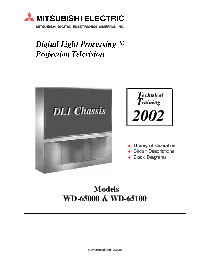
Image preview - the first page of the document

>> Download dl1_training_manual_533 documenatation <<
Text preview - extract from the document
MITSUBISHI ELECTRIC
MITSUBISHI DIGITAL ELECTRONICS AMERICA, INC.


Digital Light ProcessingTM
Projection Television


                                                     Technical
                                                     Training
        DL1 Chassis
                                                   2002
                                                  Theory of Operation
                                                  Circuit Descriptions
                                                  Block Diagrams


                    Models
             WD-65000 & WD-65100


                         www.mitsubishi-tv.com
                                        WD-65000 Training Manual

                                                          CONTENTS


Chapter 1 - Introduction ............................................................................................................... 1-1

Chapter 2 - Digital Light ProcessingTM System ........................................................................... 2-1
       DLP System ....................................................................................................................... 2-1
       Basic Signal Processing ..................................................................................................... 2-4
       Interlace to Progressive Scan Conversion ............................................................................ 2-5
       Formatter ............................................................................................................................ 2-7

Chapter 3 - Disassembly ............................................................................................................... 3-1
       Cabinet Front Disassembly ................................................................................................. 3-2
       Cabinet Rear Disassembly .................................................................................................. 3-2
       Module Disassembly .......................................................................................................... 3-3
       Chassis Assembly .............................................................................................................. 3-4

Chapter 4 - Lamp Replacement & Filter Cleaning ..................................................................... 4-1
       Lamp Box Removal ............................................................................................................. 4-2
       Lamp Box Installation ......................................................................................................... 4-3
       Air Filter Cleaning ............................................................................................................... 4-4

Chapter 5 - Option Menu & LED Diagnostic Mode ...................................................................... 5-1
       Option Menu ....................................................................................................................... 5-1
       LED Diagnostic Mode ......................................................................................................... 5-3

Chapter 6 - Optical Unit Adjustments ........................................................................................... 6-1
       Required Disassembly ........................................................................................................ 6-2
       Preparation for Adjustment .................................................................................................. 6-3
       Adjustment and Locking Screws ......................................................................................... 6-5
       Adjustments ....................................................................................................................... 6-6

Chapter 7 - Electrical Adjustments ............................................................................................... 7-1
       Service Adjustment Mode ................................................................................................... 7-1
       Adjustment Functions ......................................................................................................... 7-2
       Function Tables .................................................................................................................. 7-3
       Test Points ......................................................................................................................... 7-5
       Auto Adjust ......................................................................................................................... 7-5

Chapter 8 - Power Supply ............................................................................................................ 8-1
       Standby Supply Regulator .................................................................................................. 8-1
       Standby Supplies ................................................................................................................ 8-2
       Lamp Power Supply ............................................................................................................ 8-2
       Switched Supplies .............................................................................................................. 8-2
       Power Loss Detection (AC Off) ........................................................................................... 8-4
       Short Protect ...................................................................................................................... 8-5

Chapert 9 - Video/Color Signal Path ........................................................................................... 9-1
      NTSC Signal Selection ....................................................................................................... 9-2
      Main Picture Video/Color Signal Path ................................................................................. 9-3
      Sub Picture Video/Color Signal Path ................................................................................... 9-4
      PCB-DSP Video/Color Signal Path ..................................................................................... 9-5

Chapter 10 - Control Circuitry ..................................................................................................... 10-1
  PCB-SIGNAL Control Circuitry ................................................................................................... 10-1
       V-Chip Circuitry ................................................................................................................ 10-2
       On Screen Display (OSD) Insertion ................................................................................... 10-3
       Lamp Control .................................................................................................................... 10-3
                                                          Page 1
                                       WD-65000 Training Manual

Chapter 11 - Sync Signal Path ...................................................................................................      11-1
  PCB-SIGNAL Sync Path ............................................................................................................    11-1
       Sync Detector circuits ......................................................................................................   11-2
  PCB-DSP Sync Signal Path ......................................................................................................      11-3
       Sync Output Circuitry .......................................................................................................   11-5

Chapter 12 - Sound Signal Path ................................................................................................ 12-1
       Sound Signal Selection ..................................................................................................... 12-1
       Main and Sub Audio Signal Paths ..................................................................................... 12-3


                                                               Page 2
                                      Chapter 1
                                    Introduction


      DMDTM
                                             Lens


                                                                         Lamp
           Color Filter


Athough user operation is similar to other Projec-             DeviceTM (DMDTM). The DLPTM system is described
tion TVs, the new WD-65000 Projection TV has                   in detail in Chapter 2.
major differences. It produces the highest quality
picture possible in the current Projection TV mar-             The WD-65000 is compatible with most TV signal
ket. To achieve this high quality picture the CRTs             formats. This is illustrated in Figure 1-1. It is com-
are replaced with a Digital Light Processing TM                patible with:
(DLPTM) System.
◦ Jabse Service Manual Search 2024 ◦ Jabse Pravopis ◦ onTap.bg ◦ Other service manual resources online : Fixya ◦ eServiceinfo