Service Manuals, User Guides, Schematic Diagrams or docs for : MITSUBISHI TV CT-29BV1 mitsubishi-ct-29bv1
<< Back | HomeMost service manuals and schematics are PDF files, so You will need Adobre Acrobat Reader to view : Acrobat Download Some of the files are DjVu format. Readers and resources available here : DjVu Resources
For the compressed files, most common are zip and rar. Please, extract files with Your favorite compression software ( WinZip, WinRAR ... ) before viewing. If a document has multiple parts, You should download all, before extracting.
Good luck. Repair on Your own risk. Make sure You know what You are doing.
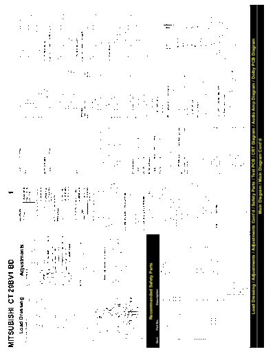
Image preview - the first page of the document

>> Download mitsubishi-ct-29bv1 documenatation <<
Text preview - extract from the document
MITSUBISHI CT 29BV1 BD 1
Load Dressing Adjustments CODE:
ADK
SETTING:
08
16
17
H-AMP-60
V-SHIFT-60
12
13
HW6
VS6
Check the VERTICAL BREATHING CORREC-
TION as follows:
1.4.2 Lead dressing 2.1 introduction MNP 70 18 H-PHASE-60 14 HP6
Leads must be dressed as shown in table 1 .4B Most service adjustments to these models are FFT 1 19 H-PHASE-TEXT 15 HPT 1. Select the VCJ adjustment display.
and the diagram (fig. 1.4C) below. The leads are made using the remote control (figure 2.1A) with VOL 74 1A H-PHASE-SECAM 16 HPS 2. Set the adjustment code to 01 (1 VBC) with
routed or clamped so that they do not come the TV in service mode. The adjustment data is HYP 1 1B H-PHASE-RGB 17 HPX buttons "2" or "8" on the remote control.
close to any heat generating or high-tension stored in an EEPROM. SCP 20 1C P-AMP-16: 9 18 PA9 3. If necessary, adjust the data value to "-31"
parts. The anode lead wire is routed such that FMP 23 1D 358 NTSC-LUMA-DELAY - using buttons "4' or "6' on the remote control.
no tension is applied to the anode cap. If the 1E 443 NTSC-LUMA-DELAY -
mounting angle of the anode cap and the route EE3W software: - NTSC (358 & 443) CHROMA DELAY 10 NTD 2.4.2 Horizontal centre
of the anode lead wires are changed, return - BG CHROMA DELAY OFFSET 9 BGD
them to the initial angle and route. CODE: SETTING: - P-AMP-60 9 PA6 Code: 09 (13 HP5) [H-PHASE-50]
TUN 1 - P-TILT-60 10 PT6
CLAMP No WIRES CLAMPED SAT 0 - C-CORRECTION-60 11 CC6 1. Connect a VCR and play a PAL-Monoscope
1 KB, KK AUD 0 - TOP-BLANKING-50 14 TB5 alignment tape.
2 DA, DM ATS - - BOTTOM-BLANKING-50 15 BB5 2. Select the VCJ adjustment display.
3 DM STD 1 - H-BLANKING-WIDTH-50 16 BW5 3. Set the adjustment code to 09 (13 HP5) with
4 DA, DD, DE, DF (3+4) SYS 2 - H-BLANKING-PHASE-50 17 BP5 buttons "2" or "8" on the remote control.
5 DD AVI 2 - TOP-BLANKING-60 18 TB6 4. Adjust the horizontal position with buttons "4'
6 DA (looped), KD AUD - - BOTTOM-BLANKING-60 19 BB6 or "6" on the remote control.
7 DY (Loop the lead twice) SPK 1 - H-BLANKING-WIDTH-60 20 BW6
8 LB, BA (Loop the lead twice) MNP 70 - H-BLANKING-PHASE-60 21 BP6 2.4.3 Horizontal width
9 KD, SC, GA (Loop the lead) NOTE: The software in the microcontroller FFT -
10 LB (Loop the lead twice), SB, Focus IC701 may be either of 2 versions -EE3 or VOL 74 OPTIONS Code: 06 (6 HW5) [H-AMP]
11 Anode lead EE3W. EE3 software is used in IC701 part no. HYP 1 CODE FUNCTION CODE
12 BA, DF(1+2) 274P755010, EE3W software is used in IC701 SCP 20 (EE3) (EE3W) 1. Connect a VCR and play a PAL-Monoscope
part no. 274P755040. FMP 23 TUN TUNER TYPE TUN alignment tape.
table 1.4B Lead-dressing table. The actual software in use is shown on the DBY 1 SAT SATELLITE ENABLE SAT 2. Select the VCJ adjustment display.
Options adjustment display - see the next WID 0 AUD AUDIO SYSTEM AUD 3. Set the adjustment code to 06 (6 HW5) with
section. 3. Press buttons "2" or "8" to increase or ATS AUTOTUNING SORT ATS buttons "2" or "8" on the remote control.
decrease the adjustment code number. table 2.2A Data values for the OPTIONS STD RECEPTION STANDARD STD 4. Adjust horizontal width with the buttons "4" or
2.1.1 Basic adjustment procedure 4. Press buttons "6" or "4" to increase or adjustments. SYS COLOUR SYSTEM SYS "6" on the remote control.
decrease the data value. AVI NO. OF AV INPUTS AVI
1.Turn the power on and enter service mode - 5. After making adjustments, press button "0', to 9. Press the 0 button to write the changes to the AVD AV DUBBING AVD 2.4.4 East-West PCC
either (EE3) press the Service switch (S701, write the adjustment data to the EEPROM. To EEPROM. EEX CHASSIS TYPE -
next to the aerial socket) and then button "9" cancel a change, press button "1', and all 10.Press the * button to select the VCJ adjust- SPK SPEAKER SW ENABLED SPK Code: 05 (5 CC5) [CORNER CORRECTION-50]
within 5 seconds (EE3W) press the MENU data adjusted since the last EEPROM write ment display. EEP EEPROM SIZE - Code: 03 (3 PT5) [PARABOLA TILT]
button to display the MAIN MENU then will be reset. 11.Press buttons 2 or 8 to select the adjustment ABG AGC GAIN ◦ Jabse Service Manual Search 2024 ◦ Jabse Pravopis ◦ onTap.bg ◦ Other service manual resources online : Fixya ◦ eServiceinfo