Service Manuals, User Guides, Schematic Diagrams or docs for : MITSUBISHI TV CT32BW1B_ch_W1
<< Back | HomeMost service manuals and schematics are PDF files, so You will need Adobre Acrobat Reader to view : Acrobat Download Some of the files are DjVu format. Readers and resources available here : DjVu Resources
For the compressed files, most common are zip and rar. Please, extract files with Your favorite compression software ( WinZip, WinRAR ... ) before viewing. If a document has multiple parts, You should download all, before extracting.
Good luck. Repair on Your own risk. Make sure You know what You are doing.
Image preview - the first page of the document

>> Download CT32BW1B_ch_W1 documenatation <<
Text preview - extract from the document
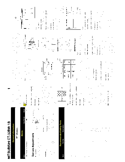
MITSUBISHI CT-32BW 1B                                                                                                                                1
                                     General Information                                                               (Insufficient degaussing causes magnetisa-
                                                                                                                       tion, giving an unfavourable effect on colour
                                                                                                                                                                        1: If beam landing divergence is to be corrected
                                                                                                                                                                           in areas (a) shown in the figure, place the
                                                                                                                                                                                                                              3: Adjust the angle between the tabs of the 6-
                                                                                                                                                                                                                                 Pole Magnet and the "B" and "R" beans to the
                                                                                                                       purity adjustment).                                 Gum Magnet on the funnel of the CRT, on               "G" beam at the centre of the screen.
                                                                                                                    3: Run the picture tube for more than thirty           axis with the corner, with the white side of the   4: Make sure that purity in each colour "R","G"
                                               W1 Chassis                                                              minutes with a white raster signal applied          magnet facing outwards.                               and "B" is maintained. If necessary repeat
                                                                                                                       giving normal beam current flow.                 2: If beam landing divergence is to be corrected         item 1(Purity), item 2 (Screen Corner Beam
                                                                                                                    4: Make sure that all electrical adjustments have      in areas (b) shown in the figure, then the Gum        Landing Correction) and item 3 (Static
                                                                                                                       been performed.                                     Magnet is placed on the funnel of the CRT             Convergence).
                                                     Matrix                                                                                                                with the white side facing the CRT.
Item                                                                                See Model             Book      1. Purity
                                                                                                                                                                        Note: The Gum Magnets will distort the raster
 Safety Precautions (See Notes).......................................................... CT-14MS1         4        Adjustment purpose:                                 shape and disturb corner convergence. To
                                                                                                                    Insure the R, G and B beams land on their           minimise the effect on raster shape and corner
                                                                                                                    respective phosphorus.                              convergence do not place the Gum Magnets
                                                                                                                                                                        closer than 50mm to the bobbin of the Deflection
                                                                                                                    Symptom when incorrectly adjusted:                  Yoke.
  Service Adjustments                                                                                               Colour patches appear, poor white uniformity.
                                                                                                                                                                        3: If correction is required in the shaded area,
                                                                                                                    Input signal:                                          move the Gum Magnet counter-clockwise until
  ITC Adjustment                                                                                                    VIDEO signal (yellow raster).                          the best position is found. If correction is                                                              Fig. 5
  ITC adjustments should be performed in the                                                                                                                               required in the unshaded areas, move the
  following sequence after replacing either the                                                            Fig 1.   Input terminal:                                        Gum Magnet in a clockwise direction until the                                                             5. Xv Correct
  CRT, Deflection Yoke or Convergence and                                                                           VIDEO IN terminal.                                     best position is found.
  Purity Magnet Assembly.                                                                                                                                                                                                                                                            Adjustment purpose:
  When not replacing parts, perform the neces-                                                                      1: Supply a VIDEO signal (yellow raster).                                                                                                                        Correct colour divergence of R, G and B
  sary adjustment only.                                         MODEL                        LENGTH                 2: With the Deflection Yoke positioned fully                                                                                                                     horizontal lines at the sides of the picture.
                                                                CT-32BW1                     45.0
◦ Jabse Service Manual Search 2024 ◦ Jabse Pravopis ◦ onTap.bg ◦ Other service manual resources online : Fixya ◦ eServiceinfo