Service Manuals, User Guides, Schematic Diagrams or docs for : Minolta Copiers CF3101 8031051wone
<< Back | HomeMost service manuals and schematics are PDF files, so You will need Adobre Acrobat Reader to view : Acrobat Download Some of the files are DjVu format. Readers and resources available here : DjVu Resources
For the compressed files, most common are zip and rar. Please, extract files with Your favorite compression software ( WinZip, WinRAR ... ) before viewing. If a document has multiple parts, You should download all, before extracting.
Good luck. Repair on Your own risk. Make sure You know what You are doing.
Image preview - the first page of the document

>> Download 8031051wone documenatation <<
Text preview - extract from the document
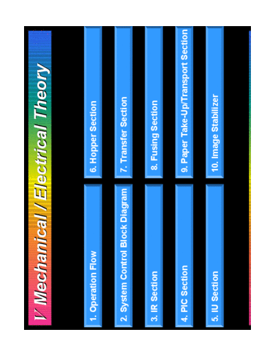
V Mechanical / Electrical Theory

1. Operation Flow                 6. Hopper Section


2. System Control Block Diagram   7. Transfer Section


3. IR Section                     8. Fusing Section


4. PIC Section                    9. Paper Take-Up/Transport Section


5. IU Section                     10. Image Stabilizer
1. Operation Flow: When the power is turned ON (1)
Power Switch ON

    Scanner Motor ON

The Scanner moves to    New Transfer Belt Unit Detection        New Fusing Unit
the shading position                                              Detection
                        1st Image Transfer Roller Retracted
Exposure Lamp ON        2nd Image Transfer Roller Retracted         Warm-up


Gain Adjustment                              Main Motor ON
                        New IU Detection
Shading Adjustment                           IU Motor ON
                                             Developing Clutch ON      Fusing
                                                                       Drive
Exposure Lamp OFF       1st Image Transfer Roller Pressed              Motor ON
                        ATDC Adjustment (New IU Only)

Scanner Home Position
                        Transfer Belt Cleaning or Prevention
                        Cleaning Blade coming OFF Control
 Scanner Motor OFF

                         To "Operation Flow: When the power is turned ON (2)"
Operation Flow: When the power is turned ON (2)
                  From "Operation Flow: When the power is turned ON (1)"


                 2nd Image Transfer Roller Pressed
                 2nd Image Transfer Roller Cleaning (Bias ON)
                 2nd Image Transfer Roller Retracted


                 1st Image Transfer Roller ATVC Control
                 Image Stabilizer
                 Color Shift Correction
                 1st Image Transfer Roller Retracted


                 Developing Clutch OFF                           Fusing
                 IU Motor OFF                                    Drive Motor
                 Main Motor OFF                                  OFF


                                             Fusing Temperature Control
Operation Flow: When Start Key is ON (1)
 Start Key ON

                                                                               Fusing Dr
     Scanner Motor ON                         Main Motor     Main Motor ON     Motor ON
                                              ON
◦ Jabse Service Manual Search 2024 ◦ Jabse Pravopis ◦ onTap.bg ◦ Other service manual resources online : Fixya ◦ eServiceinfo