Service Manuals, User Guides, Schematic Diagrams or docs for : Minolta Copiers CF3101 LINKFILE T69_70

<< Back | Home

Most service manuals and schematics are PDF files, so You will need Adobre Acrobat Reader to view : Acrobat Download Some of the files are DjVu format. Readers and resources available here : DjVu Resources
For the compressed files, most common are zip and rar. Please, extract files with Your favorite compression software ( WinZip, WinRAR ... ) before viewing. If a document has multiple parts, You should download all, before extracting.
Good luck. Repair on Your own risk. Make sure You know what You are doing.


Image preview - the first page of the document
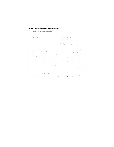
T69_70


>> Download T69_70 documenatation <<

Text preview - extract from the document
Power Supply-Related Malfunctions
(1)       Copier is not energized at all.

                                      Relevant Electrical Parts
IO Board (PWB-IO)                                 DC Power Supply 1 (PU1)
                                                  DC Power Supply 2 (PU2)


                                                       WIRING
 Step                    Check Item                   DIAGRAM      Result         Action
                                                      (Location)
                                                                            Check wiring
           Is a power voltage supplied across
      1                                                  30-H       NO      between the wall
           PJ3PU1-1 and 3 on PU1?
                                                                            outlet and PJ3PU1.
           Are the fuses (F1 and F2) on PU1 con-
      2                                                   --        NO      Change PU1.
           ducting?
           Is a power voltage supplied across
      3                                                  30-F       NO      Change PU1.
           CN1PU2-1 and 2 on PU2?
      4    Is the fuse (F1) on PU2 conducting?            --        NO      Change PU2.
           Is DC5 V being output from CN2PU2-3
      5                                                  31-F       NO      Change PU2.
           on PU2?
           Is DC5 V being input to PJ15PU1-1 on
      6                                                  28-F       NO      Change PU2.
           PU1?
           Is DC5 V being input to PJ1IO-3 on the                   NO      Change PU1.
      7                                                  14-E
           IO Board?                                               YES      Change PWB-IO.
(2)       Only the Power Supply Cooling Fan rotates.

                                      Relevant Electrical Parts
PIC Board (PWB-PIC)                                DC Power Supply 1 (PU1)
                                                   DC Power Supply 2 (PU2)


                                                       WIRING
 Step                    Check Item                   DIAGRAM      Result          Action
                                                      (Location)
           Is DC3.3 V being output from PJ9PU1-1
      1                                                  29-F       NO      Change PU1.
           on PU1?
           Is DC5 V being output from CN2PU2-2
      2                                                  31-F       NO      Change PU2.
           on PU2?
           Is DC3.3 V being input to PJ1PIC-1 on                   YES      Change PWB-PIC.
      3                                                  32-C
           PWB-PIC and DC5 V to PJ1PIC-3?                           NO      Check the wiring.

(3)       Control panel indicators do not light.

                                      Relevant Electrical Parts
Image Processing Board (PWB-C)                     DC Power Supply 3 (PU201)
Control Panel (UN201)


                                                       WIRING
 Step                    Check Item                   DIAGRAM      Result          Action
                                                      (Location)
                                                                            Reconnect or
           Is the I/F cable between the IR and
      1                                                   --        NO      change the I/F
           engine connected properly?
                                                                            cable.
                                                                            Check the wiring
           Is a power voltage being applied across
      2                                                  22-H       NO      from the wall outlet
           CN3PU201-1 and 2 on PU201?
                                                                            to CN3PU201-1/2.
      3    Is the fuse (F1) on PU201 conducting?          --        NO      Change PU201.
           Is DC5.1 V being output from
      4    CN2PU201-1 on PU201 and DC24 V                22-H       NO      Change PU201.
           from CN2PU201-3?
           Is PJ12C on PWB-C securely con-
      5                                                  26-E       NO      Reconnect.
           nected?
                                                                    NO      Reconnect.
           Is CN12 on UN201 securely con-
      6                                                  24-F               Change UN201.
           nected?                                                 YES
                                                                            Change PWB-C.


◦ Jabse Service Manual Search 2024 ◦ Jabse PravopisonTap.bg ◦ Other service manual resources online : FixyaeServiceinfo