Service Manuals, User Guides, Schematic Diagrams or docs for : Minolta Copiers Di620 1155032
<< Back | HomeMost service manuals and schematics are PDF files, so You will need Adobre Acrobat Reader to view : Acrobat Download Some of the files are DjVu format. Readers and resources available here : DjVu Resources
For the compressed files, most common are zip and rar. Please, extract files with Your favorite compression software ( WinZip, WinRAR ... ) before viewing. If a document has multiple parts, You should download all, before extracting.
Good luck. Repair on Your own risk. Make sure You know what You are doing.
Image preview - the first page of the document
>> Download 1155032 documenatation <<
Text preview - extract from the document
                                                                      MINOLTA CO., LTD., SERVICE ENGINEERING DIVISION
                                                                                                           PAGE NO. : 1/2
                   SERVICE BULLETIN
                                                                       PROBLEM            FUNCTION              SAFETY

                                                                                        SERVICEABILITY          OTHERS

MODEL NAME :       Di620                                                OTHERS          PERFORMANCE           CORRECTION

                                                                                      SAFETY REGULATION         OTHERS
MODEL CODE :       1155
           NO. :   032
       DATE :      990428
    SUBJECT :      COVER CHANGE


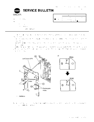
In order to make it possible to install the Finishers FN-102 and FN-502, the following changes have been
implemented :
1. Two rectangular holes for the installation of the Finisher have been added to the Left Cover-Fnt (01) and Left
   Cover-Rr (02).
2. Due to the addition of the rectangular holes in the Left Cover-Fnt (01) and Left Cover-Rr (02), the new Covers (03)
   are removable.
In addition, because of differences in the way parts are installed, there is a possibility that the Left Cover-Rr (02) and
Left Cover-Upr may interfere with each other. To prevent this, the shape of the Plate (04) has been changed to
prevent interference.


                                                                         04
                                     04
                   Left Cover-UPR


        02


                            Rectangular
                            Holes

      03                                         01
                               03
                                                 Rectangular
                                                 Holes


     03 Additions


NOTE: The new Covers (03) must be installed with the new Left Cover-Fnt (01) and Left Cover-Rr (02) as a set in
      premodification machines.


                                                                                             PCJ-242iA PRINTED IN JAPAN
  S/B NO. :   1155-032                                                                      PAGE NO. : 2/2


              BEFORE MODI.             AFTER MODI.                            QTY
NO.    F-IND         PART NO.       PART NO.         F-IND        PART NAME            I   SE/NO.   AREA


01    02-12AA      1155-1068-01   1155-1068-02   02-12AB     LEFT COVER-FNT   1      1 Y 003821     0000

02    02-10AA      1155-1069-02   1155-1069-03   02-10AB     LEFT COVER-RR    1      1 Y 003821     0000

03                                1139-1039-01   02-31AA     COVER                   4 S 003821     0000

04    06-30AA      1075-1009-01   1075-1009-02   06-30AB     PLATE            1      1 Y 002902     0000


                                                                              PCJ-247iA PRINTED IN JAPAN
◦ Jabse Service Manual Search 2026 ◦ Jabse Pravopis ◦ onTap.bg ◦ Other service manual resources online : Fixya ◦ eServiceinfo