Service Manuals, User Guides, Schematic Diagrams or docs for : Mitac mitac 8575a
<< Back | HomeMost service manuals and schematics are PDF files, so You will need Adobre Acrobat Reader to view : Acrobat Download Some of the files are DjVu format. Readers and resources available here : DjVu Resources
For the compressed files, most common are zip and rar. Please, extract files with Your favorite compression software ( WinZip, WinRAR ... ) before viewing. If a document has multiple parts, You should download all, before extracting.
Good luck. Repair on Your own risk. Make sure You know what You are doing.
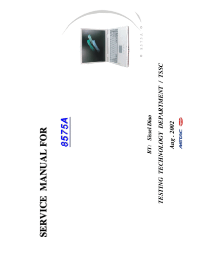
Image preview - the first page of the document

>> Download mitac 8575a documenatation <<
Text preview - extract from the document
SERVICE MANUAL FOR

                    8575A


                                             8 5 7 5 A

                  BY: Sissel Diao

     TESTING TECHNOLOGY DEPARTMENT // TSSC
     TESTING TECHNOLOGY DEPARTMENT TSSC
                   Aug . 2002
                                         8575A N/B Maintenance
Contents

1. Hardware Engineering Specification ...........................................................................                          4

  1.1 Introduction ......................................................................................................................... 4
  1.2 System Hardware Parts .......................................................................................................... 6
  1.3 Other Functions .................................................................................................................... 42
  1.4 Peripheral Components ........................................................................................................... 47
  1.5 Power Management ............................................................................................................... 50
  1.6 Appendix 1: SiS961 GPIO Definitions ......................................................................................... 52
  1.7 Appendix 2: H8 Pins Definitions ................................................................................................ 53

2. System View and Disassembly ....................................................................................                        59
  2.1 System View ......................................................................................................................... 59
  2.2 System Disassembly ............................................................................................................... 62

3. Definition & Location of Connectors / Switches ..............................................................                           81
  3.1 Mother Board ....................................................................................................................... 81
  3.2 DC Power Board ................................................................................................................... 84
  3.3 ESB Board ........................................................................................................................... 85
  3.4 Touch-pad ........................................................................................................................... 86
  3.5 Daughter Board .................................................................................................................... 86


                                                                                                                                                 1
                                          8575A N/B Maintenance
Contents

4. Definition & Location of Major Component ..................................................................                               87
   4.1 Mother Board ....................................................................................................................... 87

5. Pin Description of Major Component ...........................................................................                            89

   5.1 Intel Pentium 4 Processor mPGA478 Socket ................................................................................. 89
   5.2 SiS650 IGUI Host / Memory Controller ....................................................................................... 95
   5.3 SiS691 MuTIOL Media I/O Controller ....................................................................................... 100
   5.4 SiS301LV / Chrontel CH7019 TV/LVDS Encoder .......................................................................... 106
   5.5 PCI1410GGU PCMCIA Controller ............................................................................................ 109
   5.6 uPD72872 IEEE1394 Controller ................................................................................................ 114

6. System Block Diagram .............................................................................................                        116

7. Maintenance Diagnostics ..........................................................................................                        117

   7.1 Introduction ......................................................................................................................... 117
   7.2 Error Codes ......................................................................................................................... 118
   7.3 Maintenance Diagnostics ......................................................................................................... 120

8. Trouble Shooting ....................................................................................................                     121

   8.1 No Power ............................................................................................................................. 122


                                                                                                                                                    2
                                          8575A N/B Maintenance
Contents

   8.2 No Display ...........................................................................................................................   129
   8.3 VGA Controller Failure LCD No Display ....................................................................................               133
   8.4 External Monitor No Display ...................................................................................................          135
   8.5 Memory Test Error ...............................................................................................................        137
   8.6 Keyboard (K/B) Touch-Pad (T/P) Test Error ...............................................................................                139
   8.7 Hard Disk Drive Test Error .....................................................................................................         141
   8.8 CD-ROM Driver Test Error .....................................................................................................           143
   8.9 USB Test Error .....................................................................................................................     145
   8.10 PIO Port Test Error .............................................................................................................       148
   8.11 Audio Failure .....................................................................................................................     150
   8.12 LAN Test Error ..................................................................................................................       153
   8.13 PC Card Socket Failure .........................................................................................................        155
   8.14 IEEE 1394 Failure ...............................................................................................................       157

9. Spare Parts List .....................................................................................................                       159

10. System Exploded Views ..........................................................................................                            182

11. Circuit Diagram ...................................................................................................                         184

12. Reference Material ................................................................................................                         217


                                                                                                                                                      3
                               8575A N/B Maintenance
1. Hardware Engineering Specification
 1.1 Introduction
    The 8575A motherboard would support the Intel
◦ Jabse Service Manual Search 2024 ◦ Jabse Pravopis ◦ onTap.bg ◦ Other service manual resources online : Fixya ◦ eServiceinfo