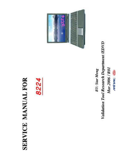
Service Manuals, User Guides, Schematic Diagrams or docs for : Mitac mitac 8224
<< Back | HomeMost service manuals and schematics are PDF files, so You will need Adobre Acrobat Reader to view : Acrobat Download Some of the files are DjVu format. Readers and resources available here : DjVu Resources
For the compressed files, most common are zip and rar. Please, extract files with Your favorite compression software ( WinZip, WinRAR ... ) before viewing. If a document has multiple parts, You should download all, before extracting.
Good luck. Repair on Your own risk. Make sure You know what You are doing.
Image preview - the first page of the document

>> Download mitac 8224 documenatation <<
Text preview - extract from the document
SERVICE MANUAL FOR

                   8224


                     BY: Star Meng
       Validation Tool Research Department /EDVD
                     Mar.2006 / R01
                                           8224 N/B Maintenance

Contents

1. Hardware Engineering Specification .............................................................................                          4
  1.1 Introduction ........................................................................................................................... 4
  1.2 Hardware System .................................................................................................................... 8
  1.3 Other Functions ...................................................................................................................... 38


                                                                   t ent
  1.4 Power Management ................................................................................................................. 44


                                                             re m
  1.5 Appendix 1: Intel ICH7-M GPIO Definitions ................................................................................. 47


                                                       ec u
  1.6 Appendix 2: W83L951DG GPIO Definitions .................................................................................. 49

                                                    S c
                                           ac l Do
2. System View and Disassembly .....................................................................................                         54


                                      iT ia
  2.1 System View ........................................................................................................................... 54
  2.2 Tools Introduction ................................................................................................................... 57

                                   M t
  2.3 System Disassembly ................................................................................................................. 58


                                        en
                                  fid
3. Definition & Location of Connectors / Switches ...............................................................                            78
  3.1 Mother Board ........................................................................................................................ 78

                            on Components ..................................................................
  3.2 Daughter Board ...................................................................................................................... 81

                         C
4. Definition & Location of Major                                                                                                            82
  4.1 Mother Board ........................................................................................................................ 82

5. Pin Description of Major Components ...........................................................................                           84
  5.1 Intel 945/945P North Bridge ...................................................................................................... 84
  5.2 Intel ICH7-M South Bridge ....................................................................................................... 90
                                                                                                                                                   1
                                             8224 N/B Maintenance

Contents

6. System Block Diagram ..............................................................................................                           101

7. Maintenance Diagnostics ...........................................................................................                           102

   7.1 Introduction ..........................................................................................................................   102


                                                                       t ent
   7.2 Error Codes ........................................................................................................................... 103


                                                                 re m
   7.3 Debug Tool ............................................................................................................................ 105


                                                           ec u
8. Trouble Shooting .....................................................................................................
                                                        S c
                                                                                                                                                 107


                                                  ac l Do
   8.1 No Power .............................................................................................................................. 109
   8.2 No Display ............................................................................................................................. 115

                                            iT ia
   8.3 TV Out Test Error .................................................................................................................. 118

                                       M t
   8.4 VGA Controller Test Error LCD No Display .................................................................................. 120


                                             en
   8.5 External Monitor No Display ...................................................................................................... 122


                                      fid
   8.6 Memory Test Error .................................................................................................................. 125


                             on
   8.7 Keyboard (K/B) Touch-Pad (T/P) Test Error ................................................................................. 127
   8.8 Hard Driver Test Error ............................................................................................................ 129

                          C
   8.9 CD-ROM Driver Test Error ...................................................................................................... 131
   8.10 USB Port Test Error ............................................................................................................... 133
   8.11 New Card Socket Test Error ..................................................................................................... 136
   8.12 Blue Tooth Test Error ............................................................................................................. 138
   8.13 Mini-PCI Socket Test Error ...................................................................................................... 140
   8.14 CardReader & IEEE1394 Socket Test Error ................................................................................. 143
   8.15 Audio Test Error ................................................................................................................... 146
                                                                                                                                                       2
                                           8224 N/B Maintenance

Contents

   8.16 LAN Test Error ..................................................................................................................... 149

9. Spare Parts List ......................................................................................................                  151

10. System Exploded Views ............................................................................................

                                                  t ent
                                                                                                                                            163


                                                re m
11. Reference Material .................................................................................................                    165


                                              ec u
                                            S c
                                          ac l Do
                                        iT ia
                                      M t
                                         en
                                     fid
                                  Con


                                                                                                                                                   3
                                   8224 N/B Maintenance

1. Hardware Engineering Specification
 1.1 Introduction

   1.1.1 General Description


                                      t ent
   This document describes the brief introduction for MiTAC 8224 portable notebook computer system.

                                    re m
                                  ec u
                                S c
                              ac l Do
   1.1.2 System Overview

                            iT ia
   The MiTAC 8224 model is designed for Intel Mobile Pentium-M Processor Yonah 533 and 667 FSB.

                          M t
                             en
   This system is based on PCI architecture and is fully compatible with IBM PC/AT specification, which has standard


                         fid
   hardware peripheral interface. The power management complies with Advanced Configuration and Power Interface.
   It also provides easy configuration through CMOS setup, which is built in system BIOS software and can be pop-up

                       on
   by pressing F2 key at system start up or warm reset. System also provides icon LEDs to display system status, such

                    C
   as AC Power indicator, Battery Power indicator, Battery status indicator, HDD,CD-ROM, NUM LOCK, CAP
   LOCK, SCROLL LOCK. It also equipped with GIGA LAN, 56K Fax MODEM, 4 USB port, S-Video and audio
   line out, SPIDIF, and internal/external microphone function.

   The memory subsystem supports DDR2 SDRAM channels (64-bits wide).

   The 945GM MCH Host Memory Controller integrates a high performance host interface for Intel Yonah processor,
                                                                                                                        4
                                 8224 N/B Maintenance
a high performance PCI Express interface, a high performance memory controller, Digital Video port (DVOB &
DVOC) interface, and Direct Media Interface (DMI) connecting with Intel ICH7-M.

The Intel ICH7-M integrates three Universal Serial Bus 2.0 Host Controllers Interface (UHCI), the Audio
Controller with Azalia interface, the Ethernet includes a 32-bit PCI controller, the IDE Master/Slave controllers, the
SATA controller and Direct Media Interface technology.


                                          t ent
Intel Graphics enhancements includes DVMT 3.0 , Zone Rendering 2.0, Quad pixel pipe rendering engine, Pixel


                                        re m
Shader 2.0 and 4x Faster Setup Engine.


                                      ec u
                                    S c
The BCM5789 is a highly integrated, cost-effective single-chip Fast Ethernet controller that provides 32-bit


                                  ac l Do
performance, PCI bus master capability, and full compliance with IEEE 802.3u 100Base-T specifications and IEEE
802.3x Full Duplex Flow Control. It also supports the Advanced Configuration Power management Interface
(ACPI).
                                iT ia
                              M t
                                 en
The Texas Instruments PCI8402 controller is an integrated single-socket IEEE 1394 open HCI host controller.and


                             fid
one-port PHY and flash media controller. This high-performance integrated solution provides the latest in IEEE
1394, SD, MMC, Memory Stick/PRO, SmartMedia, and xD technology.


                          Con
The ALC880 2-Channel High Definition Audio Codec with UAA (Universal Audio Architecture), featuring a 24-bit
two-channel DAC and two stereo 20-bit ADCs, are designed for commercial Notebook PC system. The ALC880
provide 2 output channels, along with flexible mixing, mute, and fine gain control functions. Also, supporting 32-bit
S/PDIF input and output functions and a sampling rate of up to 96kHz.

The W83L951D is a high performance microcontroller on-chip supporting functions optimized for embedded
control. These include ROM, RAM, four types of timers, a serial communication interface, optional I
◦ Jabse Service Manual Search 2024 ◦ Jabse Pravopis ◦ onTap.bg ◦ Other service manual resources online : Fixya ◦ eServiceinfo